Quartz64

The Quartz64 is the most recent Single Board Computer offering from PINE64, with Model A initially released in June of 2021 and Model B in May of 2022. It is powered by a Rockchip RK3566 Quad-Core ARM Cortex A55 64-Bit Processor with a MALI G-52 GPU.
Key features include a PCIe x4 open-ended slot (model A) or M.2 slot (model B) using a single Gen2 lane electrically, and the use of LPDDR4 RAM.
The Quartz64 is available in two LPDDR4 system memory options: 4 GB and 8 GB. For booting, there is an eMMC module socket (supporting up to 128 GB) and microSD slot, as well as a footprint to solder on an SPI flash chip. The board is equipped with HDMI, 1x USB 3.0 Type-A host, 3x USB 2.0 host, Gigabit Ethernet, SATA (model A), GPIO Bus, MiPi DSI interface, e-ink interface (model A), eDP interface (model A), touch panel interface (model A), MiPi CSI interface, as well as many other device interfaces such as UART, SPI, I2C, for makers to integrate with sensors and other peripherals. Many different Operating Systems (OS) are freely available from the open source community, such as Linux (Ubuntu, Debian, Arch), BSD, and Android.
Software releases
Under Quartz64 Software Releases you will find a complete list of currently supported operating system images, which work with the Quartz64, as well as other related software.
Getting started
Flashing the device
Natively the board only supports booting the platform firmware from SPI, the eMMC or a microSD card, see boot order. The platform firmware loaded from there (U-Boot, EDK2, ...) may then allow loading kernels from additional storage mediums or even the network, and they will have their own boot order.
The board can be booted by flashing your chosen operating system to a microSD card using another device and inserting the microSD card into the Quartz64, see the article Getting started. Flashing the eMMC is possible by booting an operating system from the microSD card and overwriting the eMMC from within the booted operating system, or by using the USB eMMC adapter.
Boot order
The hardware boot order of the Quartz64 is:
- SPI NOR flash
- SPI NAND flash
- eMMC
- microSD card
SoC and Memory Specifications
- Based on Rockchip RK3566
CPU Architecture
- Quad-core ARM Cortex-A55 at 1.8 GHz (up to 1.6 GHz on model "Zero")
- AArch32 for full backwards compatibility with ARMv7
- ARM Neon Advanced SIMD (single instruction, multiple data) support for accelerated media and signal processing computation
- Includes VFP hardware to support single and double-precision operations
- ARMv8 Cryptography Extensions
- Integrated 32KB L1 instruction cache and 32KB L1 data cache per core
- 512KB unified system L3 cache
- TrustZone technology support
- 22nm process, believed to be FD-SOI
GPU (Graphics Processing Unit) Capabilities
- Mali-G52 2EE Bifrost GPU@800MHz
- 4x Multi-Sampling Anti-Aliasing (MSAA) with minimal performance drop
- 128KB L2 Cache configurations
- Supports OpenGL ES 1.1, 2.0, and 3.2
- Supports Vulkan 1.0 and 1.1
- Supports OpenCL 2.0 Full Profile
- Supports 1600 Mpix/s fill rate when at 800MHz clock frequency
- Supports 38.4 GLOP/s when at 800MHz clock frequency
NPU (Neural Processing Unit) Capabilities
- Neural network acceleration engine with processing performance of up to 0.8 TOPS
- Supports integer 8 and integer 16 convolution operations
- Supports the following deep learning frameworks: TensorFlow, TF-lite, Pytorch, Caffe, ONNX, MXNet, Keras, Darknet
Please note that no NPU is present on model "Zero".
System Memory
- RAM Memory Variants: 2GB (SOQuartz only), 4GB, 8GB LPDDR4.
Network
- 10/100/1000Mbps Ethernet
- Easily sustains >910 Mbit/s in a
--bidir(i.e. sending and receiving at the same time) iperf3 TCP test.
- Easily sustains >910 Mbit/s in a
- Wi-Fi 802.11 b/g/n/ac with Bluetooth 5.0 (optional on model A, built in on model B)
Storage
- microSD - bootable, supports SDHC and SDXC, storage up to 2TB
- USB
- Model A: 2 USB 2.0 host ports, 1 USB 2.0 OTG port, 1 USB 3.0 host port
- Model B: 1 USB 2.0 host port, 1 USB 2.0 OTG port, 1 USB 3.0 host port
- one native SATA 3.0 6Gb/s Port (only on model A, shared with USB 3.0 host port) (removed in newer revisions due to electrical signalling issues it caused)
- optional eMMC module from 8GB up to 128GB
- 64 Mbit (8 MByte) SPI flash (Model B only), part number 25Q64DWZPIG in the schematic
eMMC Speeds
On a 64 GB eMMC module:
 $ sudo hdparm -tT /dev/mmcblk1

 /dev/mmcblk1:
  Timing cached reads:   2368 MB in  2.00 seconds = 1184.46 MB/sec
  Timing buffered disk reads: 452 MB in  3.01 seconds = 149.98 MB/sec
Expansion Ports
- HDMI
- eDP - 4 lanes of 2.7Gbps, up to 2560x1600@60Hz (only on model A)
- DSI - Display Serial Interface, 4 lanes MiPi, up to 1440P on model A, 2 lanes MiPi, up to 1080p on model B
- CSI - CMOS Camera Interface, 4 lanes MiPi up to 8 mega pixel on model A, 2 lanes MiPi up to 5 mega pixel on model B
- TP - Touch Panel Port, SPI with interrupt on model A
- RTC - Real Time Clock Battery Connector
- VBAT - Lithium Battery Connector with temperature sensor input on model A
- Wi-Fi/BT Module Header - SDIO 3.0 and UART on model A, built-in Wi-Fi/BT Module on model B
- 2x20 pins "Pi2" GPIO Header on model B, 2x10 pins GPO header on model A
- PCIe x4 open ended slot on model A, m.2 slot on model B, one Gen2 lane due to SoC constraints
- On Model A, the slot provides 10W of power for the 3.3V supply and however much power your 12V input power supply provides on the 12V supply
The PCIe implementation on the RK3566 is much more compatible with a wide range of devices compared to the one on the RK3399 used on the ROCKPro64. This means a lot more devices should work (excluding dGPUs due to a lack of cache snooping ability).
Combo PHYs

Several of the I/O options on the RK3566 used in the Quartz64 are using the same I/O lines, meaning that they cannot be used at the same time. The above diagram illustrates how they are connected.
In particular, USB 3.0 and the SATA connector on the board are mutually exclusive, and the PCI-e 2.0 lane can be reconfigured into a second SATA port, though an adapter cable needs to be fashioned for this to be useful.
GPIO Pins (Quartz64 Model A)
Attention! GPIOs are 3.3V!
| Assigned To | Pin no. | Pin no. | Assigned To |
|---|---|---|---|
| 3.3 V | 1 | 2 | 5 V |
| I2C3_SDA_M0 a,b | 3 | 4 | 5 V |
| I2C3_SCL_M0 a,b | 5 | 6 | GND |
| CPU_REFCLK_OUT | 7 | 8 | UART2_TX_M0_DEBUG |
| GND | 9 | 10 | UART2_RX_M0_DEBUG |
| SPI1_MOSI_M1 | 11 | 12 | UART0_TX a |
| SPI1_MISO_M1 | 13 | 14 | UART0_RX a |
| SPI1_CLK_M1 | 15 | 16 | GND |
| SPI1_CS0_M1 | 17 | 18 | SPDIF_OUT c |
| GND | 19 | 20 | 3.3V |
Notes
- can be a PWM pin
- pulled high to 3.3V through 2.2kOhm resistor
- low-pass filtered with cutoff of 220 MHz
Source: Page 28 of File:Quartz64 model-A schematic v1.0 20201215.pdf.
GPIO Pins (Quartz64 Model B)
Attention! GPIOs are 3.3V!
Interesting alternate pin configurations are listed in [brackets].
| Assigned To | Pin no. | Pin no. | Assigned To |
|---|---|---|---|
| 3.3 V | 1 | 2 | 5 V |
| [I2C3_SDA_M0] GPIO1_A0_3V3 | 3 | 4 | 5 V |
| [I2C3_SCL_M0] GPIO1_A1_3V3 | 5 | 6 | GND |
| GPIO3_C4_3V3 | 7 | 8 | UART2_TX |
| GND | 9 | 10 | UART2_RX |
| [SPI1_CS0_M1] GPIO3_A1_3V3 | 11 | 12 | GPIO3_A3_3V3 [I2S3_SCLK_M0] |
| [I2S3_MCLK_M0] GPIO3_A2_3V3 | 13 | 14 | GND |
| GPIO3_B0_3V3 | 15 | 16 | GPIO3_B1_3V3 |
| 3.3V | 17 | 18 | GPIO3_B2_3V3 |
| GPIO4_C3_3V3 | 19 | 20 | GND |
| GPIO4_C5_3V3 | 21 | 22 | GPIO3_C1_3V3 [SPI1_MOSI_M1] |
| GPIO4_C2_3V3 | 23 | 24 | GPIO4_C6_3V3 |
| GND | 25 | 26 | GPIO4_D1_3V3 |
| I2C4_SDA_M0 | 27 | 28 | I2C4_SCL_M0 |
| GPIO3_B3_3V3 | 29 | 30 | GND |
| GPIO3_B4_3V3 | 31 | 32 | GPIO3_C2_3V3 [SPI1_MISO_M1] |
| [SPI1_CLK_M1] GPIO3_C3_3V3 | 33 | 34 | GND |
| [I2S3_LRCK_M0] GPIO3_A4_3V3 | 35 | 36 | GPIO3_A7_3V3 |
| [SPDIF_TX_M0] GPIO1_A4_3V3 | 37 | 38 | GPIO3_A6_3V3 [I2S3_SDI_M0] |
| GND | 39 | 40 | GPIO3_A5_3V3 [I2S3_SDO_M0] |
Source: Page 24 of the board schematics.
Quartz64 Board Information, Schematics, and Certifications
Model "A"
Model "A" dimensions: 133mm x 80mm x 19mm
Input Power: DC 12V @ 3A 5.5mmOD/2.1mmID center-positive Barrel DC Jack connector
Quartz64 Model "A" SBC Schematic and PCB Board Resource:
- Quartz64 Model "A" SBC Schematic ver 2.0 20210427 PDF file
- Quartz64 Model "A" SBC PCB Connector placement PDF file
Certifications:
- Disclaimer: Please note that PINE64 SBC is not a "final" product and in general certification is not necessary. However, PINE64 still submit the SBC for FCC and CE certification and obtain the certificates to proof that SBC board is capable on passing the testing. Please note a final commercial product needs to performs its owns testing and obtains its owns certificates.
- Quartz64 model-A CE Certificate
- Quartz64 model-A FCC Certificate
Model "B"
Model "B" dimensions: 85mm x 56mm x 18.8mm
Input Power: DC 5V @ 3A 3.5mmOD/1.35mmID center-positive Barrel DC Jack connector
Quartz64 Model "B" SBC Schematic and PCB Board Resource:
- Quartz64 Model "B" SBC Schematic ver 1.3 20220124 PDF file
- Quartz64 Model "B" SBC PCB Connector placement PDF file
- Please note that v1.2 and V1.3 schematic and component placement are identical, just some component value changed.
- Note: Model B uses a Molex PicoBlade compatible connector for the RTC battery. The Pine64 Backup Battery Holders come with a JST PH type connector. To use the Pine64 RTC Backup Battery Holder, the connector on the battery holder will need to be modified with a PicoBlade type connector.
Model "Zero"
Model "Zero" dimensions: 85mm x 56mm x 18.8mm
Input Power: DC 5V @ 3A 3.5mmOD/1.35mmID center-positive Barrel DC Jack connector
Quartz64 Model "Zero" SBC Schematic and PCB Board Resource:
- Quartz64 Model "Zero" SBC Schematic ver 1.0 20240428 PDF file
- Quartz64 Model "Zero" SBC PCB Component placement (top side) PDF file
- Quartz64 Model "Zero" SBC PCB Component placement (bottom side) PDF file
Datasheets for Components and Peripherals
Rockchip RK3566 SoC information (model Zero using RK3566T which CPU speed clock at 1.6GHz and np NPU present):
- Rockchip RK3566 ver 1.0 datasheet, already got release permission from Rockchip
- Rockchip RK3566 and RK3568 TRM (Technical Reference Manual)
Rockchip PMU (Power Management Unit) Information:
- Rockchip RK817 ver 1.01 datasheet for Quartz64 model A
- Rockchip RK809 ver 1.01 datasheet for Quartz64 model B and SOQuartz
LPDDR4 (200 Balls) SDRAM:
eMMC information:
- PINE64 eMMC module schematic
- PINE64 USB adapter for eMMC module V2 schematic
- PINE64 USB adapter for eMMC module PCB in JPEG
- 16GB Foresee eMMC Datasheet
- 32GB/64GB/128GB SanDisk eMMC Datasheet
SPI NOR Flash information:
E-ink Panel information:
- Eink 10.3" 1872x1404 ES103TC1 Flex Panel Specification
- Eink 10.3" 1872x1404 ES103TC1 Glass Panel Specification
- TPS65185x PMIC for E-Ink Enabled Electronic Paper Display Datasheet
LCD Touch Screen Panel information:
- 7.0" 1024x600 TFT-LCD Panel Specification
- Touch Panel Specification
- GOODiX GT911 5-Point Capacitive Touch Controller Datasheet
Ethernet PHY information:
Wi-Fi/BT module info:
- Azurewave CM256SM 11AC Wi-Fi + Bluetooth5.0 Datasheet for model "A" and "B"
- AICSemi AIC8800DC 11AX Wi-Fi + Bluetooth5.2 Datasheet for model "Zero"
IR LED:
Enclosure information:
- Playbox Enclosure 3D file
- ABS Enclosure 3D file
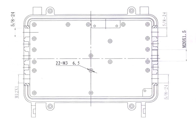
- Outdoor Aluminum Cast Dust-proof IP67 Enclosure Drawing
- 3D Printable Enclosure for Model A
- Open Frame for Model A
Connector information:
- 2.0mm PH Type connector specification use in Lithium Battery (VBAT) port (Model A)
- 1.25mm Picoblade Type connector specification used in RTC Battery port (Model B)
- 0.5mm Pitch cover type FPC connector specification use in DSI port, TP port and CSI port
Development efforts
Main Article: Quartz64 Development
Information and resources of the ongoing development effort for the Quartz64 can be found on the Quartz64 Development page, where the current status of various board functions can be found, and whether they have landed in upstream.
Enclosures
Note: Please expand this section with more cases known to work.
Model "A"
All enclosures that fit the ROCKPro64 should fit the Quartz64 Model "A", as the I/O has been laid out the same on purpose.
- Model A Acrylic Open Enclosure - but see the troubleshooting section below.
- RockPro64 Premium Aluminium Case
- ROCKPro64#3D printable ITX mounting brackets (Not an enclosure but allows to mount the board in an ATX/ITX case)
Model "B"
- Model B Acrylic Open Enclosure
- the ROCK64 aluminium enclosure does not work, as the DC input jack is placed differently
Troubleshooting
Stability/Boot Issues With Missing Battery Shunt
If there is no battery plugged into the board, the jumper labelled "ON/OFF_BATT" must be in place. If this is set wrong, stability issues such as failures to boot will occur. This affects model A only
No Ethernet Connectivity
Make sure the kernel is built with CONFIG_MOTORCOMM_PHY set to y. Building it as a module (m) and then relying on module auto-loading is unlikely to work, because if the generic PHY driver is built in it will bind to the PHY first, unless you include the motorcomm module in your initramfs.
Note: Starting with Debian's 6.1~rc3-1~exp1 kernel the module is included, but set to m and I (Diederik) have verified that it gets included in the initramfs and works on Model-A and Model-B with the Quartz64#Plebian images.
"Model A" Acrylic Case Doesn't Fit
The Quartz64 does not really fit onto the bottom plate of the Model A Acrylic Open Enclosure. This is because the "Mic" connector at the bottom of the board interferes with one of the posts. A workaround is to find out which post that is (you have a 50% chance of guessing it right, accounting for rotating the board) and then filing away the corner of the post pointing inwards by a few millimeters.

An alternate solution may be to place plastic spacers with a smaller outer diameter in between the acrylic bottom plate posts and the SBC board.
No GPU Acceleration with Debian "Bullseye" Userland
Debian Bullseye ships a Mesa version that is too old to contain the required patches for the RK356x SoC's GPU. Upgrade to Bookworm.
Wireless Connectivity Doesn't Work
ROCKPro64 wireless module may have CYW43455 or CYW43456 chips on board (not sure if this is the same for Quartz64 model B). Both chips are supported by brcmfmac Wi-Fi driver and btbcm Bluetooth driver.
For CYW43455 drivers attempt to load /lib/firmware/brcm/brcmfmac43455-sdio.bin for Wi-Fi and /lib/firmware/brcm/BCM4345C0.hcd for Bluetooth. Corresponding firmware files for CYW43456 are /lib/firmware/brcm/brcmfmac43456-sdio.bin and /lib/firmware/brcm/BCM4345C5.hcd.
On Manjaro firmware files for both Bluetooth and Wi-Fi on CYW43456 on are provided by ap6256-firmware package (pacman -S ap6256-firmware).
However for CYW43455 wi-fi firmware is in the linux-firmware package and bluetooth is in the firmware-raspberrypi (pacman -S linux-firmware firmware-raspberrypi). linux-firmware package is missing device specific symlinks for quartz64-a. To create them execute:
# ln -s brcmfmac43455-sdio.bin /lib/firmware/brcm/brcmfmac43455-sdio.pine64,quartz64-a.bin
# ln -s brcmfmac43455-sdio.AW-CM256SM.txt /lib/firmware/brcm/brcmfmac43455-sdio.pine64,quartz64-a.txt
As of 2022-10-19 device tree in mainline kernel for Quartz64 model A has wrong configuration for the Bluetooth driver. Patch is submitted to the LKML and accepted and included upstream in 6.1-rc7. It's possible to modify dtb file provided by the current kernel using device tree compiler to enable Bluetooth or perform make dtbs in the patched kernel tree to get updated dtb file (arch/arm64/boot/dts/rockchip/rk3566-quartz64-a.dtb). Issue manifests itself with following errors in `dmesg`:
 command 0x0c03 tx timeout
 Bluetooth: hci0: BCM: Reset failed (-110)
How-To
Connect Debug UART
The easiest way to get debug output is to connect a 3.3V 1.5mbaud capable UART adapter to the board.
To connect it, connect the ground lead to pin 6, and the RX/TX leads to pins 8 and 10 (consider swapping them if you get no output, things are often mislabeled). These pins are "UART2" in the above GPIO table.
Open a serial terminal at 1500000 bauds, e.g.
$ picocom -b 1500000 /dev/ttyUSB0
Disable Heartbeat LED (Linux)
The flashing LED is called the "heartbeat LED", it blinks in a heart rhythm like fashion once the kernel is running. To disable it, you can run
# echo none > /sys/class/leds/user-led/trigger
On model A LED device is called "diy-led", not "user-led".
On a system with systemd, you can do this as soon as the system is ready to be logged in with a systemd unit like this:
[Unit]
Description=Turn off heartbeat LED
Wants=multi-user.target
After=multi-user.target

[Install]
WantedBy=multi-user.target

[Service]
Type=simple
ExecStart=sh -c 'echo none > /sys/class/leds/user-led/trigger'
Place it in /etc/systemd/system/user-led.service, and run
# systemctl daemon-reload
# systemctl enable user-led.service
Upon rebooting, you will now notice that the heartbeat LED will blink during boot-up, but stops blinking as soon as the multi-user target is reached (i.e. the user can log in).
SATA on model A
On model A USB 3.0 and SATA ports are using the same I/O line and can't be used simultaneously. By default USB 3.0 is enabled in Linux device tree and SATA is disabled. FDT modifications are required to turn SATA on.
Following script is tested on Manjaro but should work on the other distributions with minimal changes. Device tree compiler package usually provides fdtput command (on Manjaro run: pacman -S dtc)
# cp /boot/dtbs/rockchip/rk3566-quartz64-a.dtb /boot/dtbs/rockchip/rk3566-quartz64-a-sata.dtb
# fdtput -t s -v /boot/dtbs/rockchip/rk3566-quartz64-a-sata.dtb /usb@fd000000 status disabled
# fdtput -t s -v /boot/dtbs/rockchip/rk3566-quartz64-a-sata.dtb /sata@fc400000 status okay
# sed -i 's#^FDT /dtbs/rockchip/rk3566-quartz64-a.dtb$#FDT /dtbs/rockchip/rk3566-quartz64-a-sata.dtb#' /boot/extlinux/extlinux.conf
# systemctl reboot
Using a PCF8574 on Model A
See Quartz64 Model A using a PCF8574.
Using a battery on Model A
See Quartz64 Model A Using a battery.
Connecting a MIPI-DSI display
See Quartz64 connecting a MIPI-DSI display.
Building Mainline U-Boot
Frequently Asked Questions
Do I Need A Fan/What Heatsink Do I Need?
You don't need a fan. The 20mm medium heatsink for Model A is plenty enough. For Model B, the fan type heatsink will do fine.
Can This Run A Minecraft Server?
Yes! Sort of. Testing on an 8GB Model A with PaperMC, User:CounterPillow was able to out-row world generation in a boat with just one player online, but aside from the slow world gen (which can be pre-generated) the server handled things like TNT explosions and mobs fine. It'll probably do okay with 1-3 players.
Do I Need The 5A Power Supply For Model A?
You only need the 5A power supply for Model A if you plan on connecting hard disk drives to the 12V header on the board.
How Much Power Does It Consume?
For Model B, it's <2W in idle (powertop tunables not set), and <5W under full CPU load (stress-ng -c4). Model A will be similar as it's the same SoC.