PineNote Development/UART

This page contains information on creating and using a UART dongle for the PineNote. The PineNote was shipped with a compatible UART dongle, but replacements are not available to order in case of loss or hardware fault. Thankfully it is not difficult to make your own from easily-acquired components and a small bit of soldering.
Fear not if you've never soldered anything before! This serves as an excellent first soldering project. Borrow the tools from a friend, local hackerspace, or tool library. Pine64 also makes a nice soldering iron themselves.
A PineNote UART dongle enables you to:
- Interact with the system boot menu
- Read system events in real time as the PineNote is used
- Fix the PineNote without opening the case if something goes wrong while flashing it
Since the PineNote is an embedded system, interfacing with it during boot is more complicated than with an ordinary computer. The UART dongle enables you to do this.
The PineNote factory firmware runs UART at a baud rate of 1500000 bps, 8 data bits, 1 stop bit, no parity and no flow control. The process by which the PineNote design was modified to include closed-case UART is documented here.
Stock dongle
The stock UART dongle included with the PineNote is a simple device that plugs directly into the PineNote's USB-C port. The dongle exposes a female USB-C port, which the user connects to their host computer to get access to the serial console UART. This design unfortunately ruled out passthrough USB connections, where the user connects to the PineNote via UART and USB simultaneously. The dongle is not currently available separately for purchase.
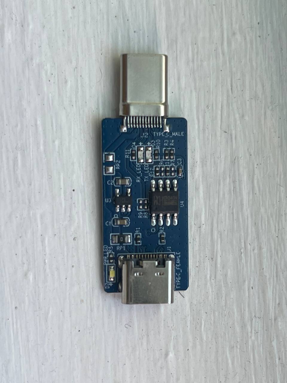
Front
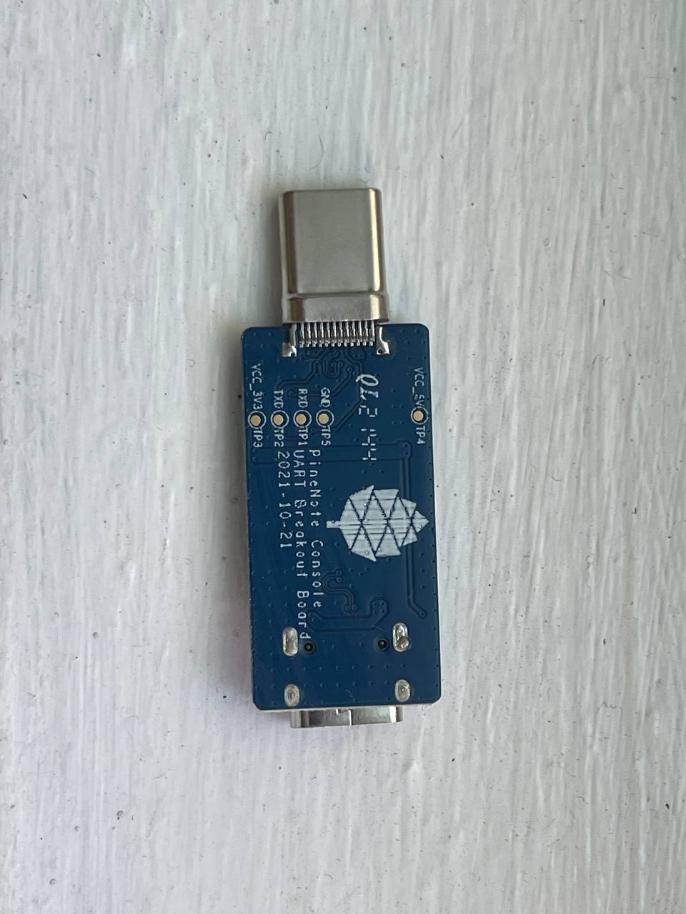
Back


Using the dongle
First, use your UART dongle to physically connect your PineNote to your computer:
- Plug the USB-UART adapter into one of your computer's USB ports
- Plug the USB-C breakout board into the USB-C port on the bottom of your PineNote; the orientation matters, so try both and remember which one works
Once the hardware is connected, we need some program on your computer to communicate over that connection with 1500000 (1.5 million) bps, 8 data bits, 1 stop bit, no parity and no flow control. Here's how you do that:
- Identify the USB-UART adapter in your
/devdirectory by runningls /devwith it plugged in, unplugging it, then again runningls /devand seeing what changed; it is likely to be called/dev/ttyUSB0 - Check your permissions; run
ls -l /dev/ttyUSB0to see which groups have access to the dongle (probablydialoutoruucp), and add your user to that group; remember you need to log out before group changes take effect - Install minicom (or some other option, but the instructions below are written for
minicom) - In a terminal window, run
minicom -D /dev/ttyUSB0 -b 1500000or runminicom --setupto specify these settings by default - Alternatively, you can also
picocomfor the connection:picocom --baud 1500000 --databits 8 --stopbits 1 --flow none --parity none /dev/ttyUSB0 - Side note: If you are often using the UART dongle, it could make sense to define a shell alias for this:
alias ppc='picocom --baud 1500000 --databits 8 --stopbits 1 --flow none --parity none /dev/ttyUSB0'
Once the software is set up, power-cycle your PineNote; as the system boots you should see text appearing in your terminal window.
You can exit the session with ctrl+a x then pressing Enter to confirm.
Run man minicom for more details.
Sending commands (minicom)
Pressing ctrl+a in minicom enables you to send keystrokes to your PineNote.
The most important of these is ctrl+c, which if sent during boot will put you in the U-Boot command prompt.
You can then type help to list possible commands.
Troubleshooting Stock UART dongle
If you don't see any text in your terminal as the PineNote boots, or the text is garbled, try the following:
- Connect your USB-C breakout board to your PineNote in the opposite orientation
- Run
minicomas sudo in case your user doesn't have appropriate permissions - Ensure you are setting the baud rate to 1500000 (1.5 million), and (less importantly because these are probably used by default) 8 data bits, 1 stop bit, no parity and no flow control
If you can see text but are having trouble sending ctrl+c to the PineNote during boot:
- Be sure you're typing
ctrl+afirst, or whatever escape sequence your terminal emulator uses - Send it right as the PineNote is booting, before the loading bar appears on screen
Building a new UART dongle

A typical self-built PineNote UART dongle design has the following components:
- A USB-C breakout board with a male connector exposing the 24 pins of the PineNote's USB-C port
- A USB-UART adapter, to plug into a USB port of the computer you'll use to interface with the PineNote
- Jump wires to connect specific breakout board pins to pins on the USB-UART adapter
- Two 1,000 Ohm through-hole resistors to splice into the jump wires
- Electrical tape or heat shrink to wrap connectors and prevent shorts
You will also need the following tools:
- Soldering iron with solder
- Wire cutters & strippers
The PineNote's internal UART system is documented in this schematic. The purpose of all 24 USB-C pins is documented on the USB-C Wikipedia page. We are interested in three sets of pins:
- The SBU1 (A8) and SBU2 (B8) side band use pins
- The CC1 (A5) and CC2 (B5) configuration channel pins
- The GND ground return pins (A1, A12, B1, and B12)
In the PineNote UART schematic you can see (on the bottom right diagram labeled USB_TYPEC_Male) the side band pins are given the labels UART2_TX_SUB1 for A8 and UART2_RX_SUB2 for B8.
The first (TX) is used for transmitting data and the second (RX) is used for receiving data, from the perspective of the PineNote.
Also note the configuration channel pins labeled TYPEC_CC1 for A5 and TYPEC_CC2 for B5.
The diagram shows they must be connected to a 3.3V source in parallel, mediated by resistors.
Per the USB-C standard, when these pins are pulled high this indicates the device should enter Debug Accessory Mode; connecting them to a voltage source & limiting the current with pull-up resistors accomplishes this.
The schematic indicates 10,000 Ohm resistors, but community member Visti Andresen (talpadk) experimented and found 1,000 Ohm resistors work better.
Our mission is to wire up pins from a USB-UART adapter to a USB-C breakout board following these requirements.
Buying components
There are many possible USB-C breakout board designs available for purchase online. One particularly useful design is a "passthrough" or "intercept" style, with both male and female USB-C ports. This design is more versatile in case you want to reuse it in other projects, and also enables you to connect to the PineNote via UART and USB at the same time. An example of this product can be found here, although you are encouraged to shop around for cheaper options. If you're fine with a bit more soldering, there is a very cheap one here.
Similarly, there are many USB-UART adapter designs available. These devices plug into your computer and expose a number of pins themselves, connecting to specific pins on the breakout board with jump wires. It is important to get a 3.3V model, or at least a model with the option of 3.3V, as a 5V source might fry the PineNote. Here is one example with jump wires included, although you are again encouraged to shop around for alternatives.
All other necessary components of our UART dongle are readily & cheaply available in many locations.
Splicing resistors

This is the only difficult part of the whole process. Your goal is to create a Y-shaped jump wire with 1,000 Ohm through-hole resistors spliced into each of the twin arms. The solitary leg will connect to a 3.3V source on your USB-UART adapter. The twin arms will connect to the configuration channel pins on your USB-C breakout board. Per the USB-C standard, when these pins are pulled high this indicates the device should enter Debug Accessory Mode; connecting them to a voltage source & limiting the current with pull-up resistors accomplishes this.
For this project you'll need:
- A soldering iron with solder
- Wire cutters & strippers
- 2x jumper wires, male/female as compatible with your board designs
- 2x 1,000 Ohm through-hole resistors
- Electrical tape or heat shrink wrap
Consider buying extra jumper wires and resistors in case you mess up. Also double-check that you have 1K resistors with this color code calculator. Although the PineNote UART schematic says to use 10K Ohm resistors, community member Visti Andresen (talpadk) experimented and found 1K is more appropriate. Assemble your Y-cable as follows:
- Graft one jump wire onto the other to form a Y shape using this technique, ensuring solitary leg end is compatible with your USB-UART adapter
- Splice resistors into the twin arms using this technique
- Splice remaining jump wire onto the ends of the resistors, ensuring ends are compatible with your USB-C breakout board
- Cover all exposed wire & resistors with electrical tape or heat shrink wrap
Assembly
Once you have acquired all necessary components, assemble the UART dongle as follows:
- Connect a jump wire from the GND pin on the USB-UART adapter to any one of the four GND pins on the USB-C breakout board (A1, A12, B1, or B12)
- Connect a jump wire from the RXD pin on the USB-UART adapter to the
UART2_TX_SUB1SBU1 pin on the USB-C breakout board (A8) - Connect a jump wire from the TXD pin on the USB-UART adapter to the
UART2_RX_SUB2SBU2 pin on the USB-C breakout board (B8) - Connect your Y-shaped jump wire from the 3.3V source pin on the USB-UART adapter to the CC1 and CC2 pins on the USB-C breakout board (A5 and B5)
- Wrap all metal connectors in electrical tape or heat shrink to prevent accidental shorts
Be very certain of your connections for the 3.3V source and its cable, as there is a real risk of irreparably frying your PineNote if they're wrong! Especially be sure you are connecting to a 3.3V source and not a 5V source.
Note that if you mix up the TX/RX pins, it will still work but the USB-C breakout board will just plug into the PineNote upside down. You can therefore choose which orientation you want by swapping the TX/RX pin connections. Experience shows that RX/TX-TX/RX connections will have the PineNote face down while connected, while RX/RX-TX/TX connections will put the PineNote face up.
Troubleshooting Custom UART dongles
If you don't see any text in your terminal as the PineNote boots, or the text is garbled, try the following:
- Ensure your GND, RX/TX, and CC jump wires are connected to the correct pins on both the USB-UART adapter and the USB-C breakout board
If you can see text but are having trouble sending ctrl+c to the PineNote during boot:
- Double-check your Y-shaped pull-up resistor cable; if this isn't working properly you'll probably be able to read text but not send text
USB passthrough (only custom-built dongles)
If your USB-C breakout board has a passthrough/intercept design, you can connect to your PineNote over USB and UART at the same time. This can be useful when you're doing development work on the PineNote boot process so you don't have to continually reconnect cables. You'll need a USB-A to USB-C cable, connecting directly from your computer's USB-A hub to your USB-C breakout board's female USB-C port. It's important to connect directly from USB-A, without any intermediate USB-C components. Note that connecting a live USB cable to your USB-C breakout board in this way dramatically increases the danger of frying your PineNote with a short, so you should only do this if all connectors are safely wrapped in electrical tape.