Difference between revisions of "PinePhone"
Jkujawinski (talk | contribs) |
m (Enhance links to Flex Pogo breakout board connector.) |
||
| Line 179: | Line 179: | ||
For a breakout board see [https://github.com/SMR404/PinephonePogoBreakout here]. For an example project see Martijn's blog post [https://blog.brixit.nl/making-a-backcover-extension-for-the-pinephone/ <i>"Making a backcover extension for the PinePhone"</i>]. | For a breakout board see [https://github.com/SMR404/PinephonePogoBreakout here]. For an example project see Martijn's blog post [https://blog.brixit.nl/making-a-backcover-extension-for-the-pinephone/ <i>"Making a backcover extension for the PinePhone"</i>]. | ||
Pine64 store currently sells the | Pine64 store currently sells the [https://pine64.com/product/pinephone-flex-break-out-board/?v=0446c16e2e66 PinePhone Flex Breakout Board]. With the pitch being 2.54 mm, this Flex Breakout Board may have leads soldered directly to the contacts for use in a solderless board. A non-soldered solution would be to use a [https://www.digikey.com/en/products/detail/te-connectivity-amp-connectors/5-520315-6/2258879 TE AMP Connector] that will accept a Flat Flexible Cable 2.54 mm pitch. | ||
=== Back cover === | === Back cover === | ||
Revision as of 00:36, 7 May 2021

The PinePhone is a smartphone created by PINE64. It is capable of running mainline Linux and is supported by many partner projects.
The Braveheart Edition of the PinePhone was the first publicly available version of the phone. It shipped without a fully functional operating system and was geared specifically towards early adopters. The Braveheart Edition's successors were the Community Editions, which featured a branded backcover and box of selected community projects. The Community Editions became available in June 2020. The Beta Edition featuring Manjaro with Plasma Mobile is the latest edition, it became available in March 2021.
Introduction
The PinePhone is not a regular phone and you might not get the latest and greatest hardware and this years' newest innovation. You will get a device with good mainline support with a great community behind it.
State of the software
First things first, the PinePhone is aimed solely at early adopters - more specifically, the only intend for these units is to find their way into the hands of users with extensive Linux experience.
Bear in mind that the software for Linux on phones is very early, with most of the software being in alpha or beta state. That's especially also the case for scalability of applications, their availability and practicability, any hardware function implementations and the firmware. The software is provided as is. There is no warranty for the software, not even for merchantability or fitness for a particular purpose.
If you have any questions regarding the current state of the software or of specific features working, please don't hesitate to ask in the community chat (see Main Page#Community and Support)!
Help and support
For any questions regarding the phone please regard the contents of this wiki page, including linked articles further below. Still have any questions regarding software, shipping or ordering? Please don't hesitate to contact the community in the bridged community channels for detailed answers and to chat with friendly people, see Main Page#Community and Support.
Mind that PINE64 is not like a regular company (see PINE64 philosophy) and that support resources are spare - the preferred way to get support quickly (issues are best solved in they're solved without delay!) is to ask in the community chat and to only contact PINE64 directly if questions couldn't be solved via the chat. The community is happy to help with any issue.
First time installation
When shipped the battery is isolated from the device using a protective plastic tab, which is required to be removed before using the phone. The battery will not charge until this is removed and the modem, WiFi and Bluetooth will not work until the battery is connected.
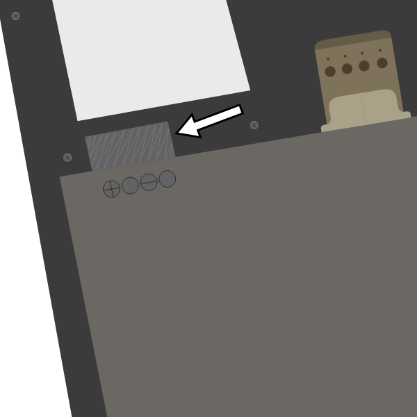
The PinePhone's SIM slot only accepts a micro SIM, please do not insert a nano SIM without an adapter. An adapter from a nano to a micro SIM might be included under tape in the camera notch of the phone's packaging. The SIM card has to be placed in the lower slot, while the microSD has to be placed in the upper slot.
To remove the sticker after unboxing the phone:
- Carefully remove the back panel using the notch in the corner of the back cover without overbending it
- Remove the battery (if the battery is stuck in the device please check this paragraph for a fix)
- Peel off the clear plastic sticker below it, which isolates the charging contacts
- Reinsert the battery
A protection foil isolates the battery for the shipping.
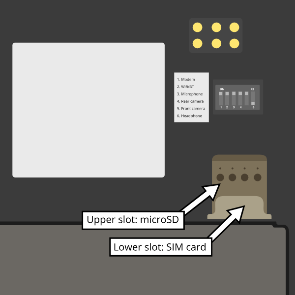
The microSD belongs in the upper slot, the micro SIM in the lower slot.


Specifications
- Dimensions: 160.5 x 76.6 x 9.2mm
- Weight: Between 180 ~ 200 grams
- SIM Card: Micro-SIM
- Display:
- Size: 5.95 inches (151mm) diagonal
- Type: HD IPS capacitive touchscreen, 16M colors
- Resolution: 1440x720, 18:9 ratio
- System on Chip: Allwinner A64
- RAM: 2GB or 3GB LPDDR3 SDRAM
- Internal Storage: 16GB or 32GB eMMC, extendable up to 2TB via microSD, supports SDHC and SDXC
- Back Camera: Single 5MP, 1/4", LED Flash
- Front Camera: Single 2MP, f/2.8, 1/5"
- Sound: Loudspeaker, 3.5mm jack & mic (jack doubles as hardware UART if killswitch 6 is deactivated)
- Communication:
- Modem: Quectel EG25-G
- LTE-FDD: B1, B2, B3, B4, B5, B7, B8, B12, B13, B18, B19, B20, B25, B26, B28
- LTE-TDD: B38, B39, B40, B41
- WCDMA: B1, B2, B4, B5, B6, B8, B19
- GSM: B2, B3, B5, B8 (850, 900, 1800, 1900 MHz)
- WLAN: Wi-Fi 802.11 b/g/n, single-band, hotspot
- Bluetooth: 4.0, A2DP
- GNSS: GPS/GLONASS/BeiDou/Galileo/QZSS, with A-GPS
- Sensors: Accelerometer, gyroscope, proximity, ambient light, compass
- Killswitches: Modem, WiFi & Bluetooth, Microphone, Cameras
- Battery: Lithium-ion, rated capacity 2800mAh (10.64Wh), typical capacity 3000mAh (11.40Wh) (nominally replaceable with any Samsung J7 form-factor battery)
- I/O: USB Type-C, USB Host, DisplayPort Alternate Mode output, 15W 5V 3A Quick Charge, follows USB PD specification
Components
| Component | Model |
|---|---|
| Touchscreen | Goodix GT917S |
| Rear camera | OmniVision OV5640 |
| Camera flash | SGMICRO SGM3140 |
| Front camera | GalaxyCore GC2145 |
| LCD | Xingbangda XBD599 |
| WiFi | Realtek RTL8723CS |
| Bluetooth | Realtek RTL8723CS |
| Modem | Quectel EG25-G |
| GNSS/GPS | Quectel EG25-G |
| Magnetometer | ST LIS3MDL |
| Ambient light / Proximity | SensorTek STK3335 |
| Accelerometer / Gyroscope | InvenSense MPU-6050 |
| Vibration motor | Unknown model |
| Notification LED | LED0603RGB |
| Volume buttons | Buttons connected to the KEYADC |
| Power button | X-Powers AXP803 |
| Battery fuel gauge | X-Powers AXP803 |
See the PinePhone Component List.
Hardware revisions
The following are all hardware revisions of the PinePhone that have existed, ordered by the time of their releases:
- Project Anakin
- "Project Don't Be Evil" – development kit (devkit)
- PinePhone v1.0 – developer batch
- PinePhone v1.1 – Braveheart
- PinePhone v1.2 – Ubports Community Edition
- PinePhone v1.2a – postmarketOS Community Edition
- PinePhone v1.2b – Manjaro Community Edition, KDE Community Edition, Mobian Community Edition, and Beta Edition
Hardware accessory
PinePhone hardware accessory compatibility
See PinePhone Hardware Accessory Compatibility for a list of devices working with the PinePhone (depending on their OS support).
USB-C connector
The USB-C can be used to power the device, and offers USB2 host and OTG possibilities, and also can make use of the USB-C capability to integrate HDMI signals. Some USB-C hubs are available that offer power throughput, USB connection, HDMI port and Ethernet connection.
Pogo pins

The PinePhone has six pogo pins on the back allowing for custom hardware extensions such as wireless charging, an IR blaster, a keyboard extension or extended battery case. The pogo pins provide access to an interrupt line, power inputs/outputs and an I2C interface.
| Interrupt | SDA | SCL |
| DCIN | USB-5V | GND |
DCIN and USB-5V are the names used in the schematics. The actual behavior of these pogo pins is not obvious based on their names. DCIN is connected both to the VBUS line of the USB Type-C connector, and to the ACIN/VBUS inputs on the PMIC. This means that, depending on a number of factors, DCIN may be at 0 V or 5 V. USB-5V is connected at the output of an LP6226 DC/DC boost converter (5 V), which in turn is fed by the PS output of the PMIC. The boost converter is enabled or disabled by a GPIO output from the A64 SoC, controlled by software (e.g. the Linux kernel). Depending on inputs and decision made by the PMIC, PS may be at the battery voltage (fed "directly" by the battery through a transistor controlled by the PMIC), or at the "USB" voltage (fed by the PMIC's ACIN/VBUS inputs). This means that depending on a number of factors, USB-5V may be at battery voltage (between 3.0 V and 4.3 V), or at 5 V.
Because the PinePhone may act as a USB host (providing 5 V at the USB Type-C connector's VBUS to a connected device) or as a USB device (drawing from a 5 V source on the USB Type-C connector's VBUS), DCIN is actually not strictly an input nor an output. Some community analysis of the PinePhone schematic (and some testing) indicates that you can connect a 5 V power supply to DCIN in order to power the phone at the PMIC's ACIN/VBUS inputs (and, as a side effect, charge the battery). This may not be safe to do in all conditions, e.g., when the phone is acting as a USB host to a connected USB device. It should also be safe to use DCIN as a power output from the PinePhone, e.g., when a USB Type-C charger is connected, you can draw current directly from the USB Type-C port's VBUS, which is provided by the charger. Please note that, when using DCIN as an output from the PinePhone, DCIN isn't "always on"; it may be 0 V. It is currently not documented on how much current can be safely drawn.
USB-5V should be safe to use as an "always on" power output from the PinePhone. Depending on a number of factors, voltage may be from 3 V to 5 V; thus, if you are using USB-5V to power your pogo-pins expansion board, you will probably need to use DC/DC converters/regulators as appropriate. USB-5V is on even while the A64 SoC is powered down.
The I2C and interrupt lines have pull-ups on the phone side. The I2C lines are pulled up to 3v3 by the phone.
For a breakout board see here. For an example project see Martijn's blog post "Making a backcover extension for the PinePhone".
Pine64 store currently sells the PinePhone Flex Breakout Board. With the pitch being 2.54 mm, this Flex Breakout Board may have leads soldered directly to the contacts for use in a solderless board. A non-soldered solution would be to use a TE AMP Connector that will accept a Flat Flexible Cable 2.54 mm pitch.
Back cover
A step file for the back cover for creating custom cases is freely available here.
Community-built accessories
- PinePhone Development Stand at Thingverse
- PinePhone Hard Case by _The3DmaN_ at Thingverse
- PinePhone Hard Case by blitzaxt at Thingverse
Serial console

The PinePhone has a serial port in the headphone connector, it's activated by the 6th contact on the dipswitch. If the switch is set to "on", the headphone connector is in audio mode, if it is set to "off" it's in UART mode. The UART serial connection can also be used for communication with other devices from the PinePhone.
The UART is 115200n8.
The pinout for the serial connector is:
- Tip: RX
- Ring: TX
- Sleeve: GND
You can buy a serial debug cable from the Pine64 Store. The store cable uses a 4 ring plug, as seen in the here, but a 3 ring plug works just as well. The cable uses a CH340 chipset based serial to USB converter, but any 3.3v serial connection can be used. Because it is a "host"/DTE it means that you need a cross modem cable (Null Modem) with TX on Tip to be connected to RX. A cable like e.g. FTDI TTL-232R-3V3-AJ which has TX on Tip and RX on Ring fits perfectly.
Killswitch configuration

The PinePhone features six switches that can be used to configure its hardware. They are numbered 1-6, with switch 1 located nearest to the modem. Their "on" position is toward the top of the phone.
| Number | Name | Explanation | Description |
|---|---|---|---|
| 1 | Modem | Pulls Q1501 gate up (FET killing modem power) | "On" enables 2G/3G/4G communication and GNSS hardware, "off" disables it. |
| 2 | WiFi / Bluetooth | Pulls up CHIP_EN | "On" enables WiFi and Bluetooth communication hardware, "off" disables it. |
| 3 | Microphone | Breaks microphone bias voltage from the SoC | "On" enables audio input from on-board microphones (not 3.5 mm jack), "off" disables it. |
| 4 | Rear camera | Pulls up PWDN on OV5640 | "On" enables the rear camera, "off" disables it. |
| 5 | Front camera | Pulls up PWDN on GC2145 | "On" enables the front camera, "off" disables it. |
| 6 | Headphone | Pulls up IN2 on analog switch BCT4717ETB | "On" enables audio input and output via the 3.5 mm audio jack, "off" switches the jack to hardware UART mode. |
Camera
The PinePhone has two cameras, OmniVision OV5640 with 5MP (up to 2592 x 1944 pixels) as rear camera and GalaxyCore GC2145 with 2MP (up to 1600 x 1200 pixels) as front camera.

Further details regarding the camera and the Megapixels camera app can be found on Martijn's blog.
Battery
The phone ships with a protective plastic sticker between the battery and the phone to protect the device from turning on during shipping.. You need to gently open the back cover, then remove the battery and finally remove the sticker and check that the pins aren't bent. Note: If the battery is stuck inside the phone, the mid screw in the lower part of the midframe needs to be slightly loosened, see here.
The supplied battery is meant to be compatible with Samsung part number EB-BJ700BBC / BBE / CBE from the 2015 J7 phone. The extended life aftermarket BBU does fit, although it is a tight fit.
The battery terminals, from the nearest to the battery edge to the nearest to the middle of battery, are as follows:
| +ve | thermistor | -ve | not connected |
The battery includes a protection circuit that isolates it in a number of fault conditions, including if it is discharged too far. The fully discharged battery can be recharged by connecting the phone to a charger with a sufficient output. Once it has charged sufficiently you will be able to boot the phone.
Modem
The PinePhone uses Quectel EG25-G as modem. AT commands are used to communicate with the modem. The software minicom can be used to send the commands under Linux.
To connect with the modem under Linux:
minicom -D /dev/ttyUSB2
AT commands
A list of documented AT commands can be found in the EC25&EC21 AT Commands Manual from Quectel. Further undocumented AT commands found by the developer megi, who reverse-engineered parts of the modem and its firmware, can be found on megi's website here.
VoLTE
The PinePhone's modem supports VoLTE and comes with a few VoLTE profiles preloaded. Most OSes try to set the correct profile automatically.
To list the available VoLTE profiles:
AT+QMBNCFG="list"

+QMBNCFG: "List",0,1,1,"ROW_Generic_3GPP",0x0501081F,201901141
+QMBNCFG: "List",1,0,0,"VoLTE-ATT",0x0501033C,201909271
+QMBNCFG: "List",2,0,0,"hVoLTE-Verizon",0x05010141,201911251
+QMBNCFG: "List",3,0,0,"Sprint-VoLTE",0x05010205,201908141
+QMBNCFG: "List",4,0,0,"Commercial-TMO_VoLTE",0x05010505,201811231
+QMBNCFG: "List",5,0,0,"Telus-Commercial_VoLTE",0x05800C43,201912031
+QMBNCFG: "List",6,0,0,"Commercial-SBM",0x05011C18,201904021
+QMBNCFG: "List",7,0,0,"Commercial-DT",0x05011F1C,201905311
+QMBNCFG: "List",8,0,0,"Reliance_OpnMkt",0x05011B38,201910161
+QMBNCFG: "List",9,0,0,"TF_Germany_VoLTE",0x05010C1B,201909201
+QMBNCFG: "List",10,0,0,"TF_Spain_VoLTE",0x05010CFA,201909261
+QMBNCFG: "List",11,0,0,"Volte_OpenMkt-Commercial-CMCC",0x05012071,201904281
+QMBNCFG: "List",12,0,0,"OpenMkt-Commercial-CT",0x05011322,201911081
+QMBNCFG: "List",13,0,0,"OpenMkt-Commercial-CU",0x05011505,201807052
To select a profile manually, select the best fitting one or a generic one if none fits:
AT+QMBNCFG="select","ROW_Generic_3GPP"
Then enable Voice over LTE using:
AT+QCFG="ims",1
And reboot the modem to apply the settings:
AT+CFUN=1,1
To check the status of VoLTE during a call, the AT command CLCC can be used:
AT+CLCC

+CLCC: 1,1,0,1,0,"",128
+CLCC: 2,1,0,1,0,"",128
APN settings
The APN setting is only required for a public Internet connection ("data") on the phone. For tested APN settings and how to apply them see PinePhone APN Settings.
Carrier support
The page PinePhone Carrier Support contains information about the frequency support of different carriers and hints on setting up cellular network connectivity.
Documents
Detailed information about the modem can be found on the page of the developer megi, including reverse-engineered parts of the firmware and its functions. There is also a document about using the modem from January 18th 2020 by megi here. A script at the end of the document showcases a way to poweroff the modem before powering off the phone, which is integrated into most of the available OSes.
Firmware update
The modem firmware can be updated to the latest version if it is outdated and dmesg returns the following message:
modem-power serial1-0: Your modem has an outdated firmware. Latest know version is EG25GGBR07A08M2G_01.002.07. Consider updating.
Pre-update checklist:
Please make sure all requirements of the checklist are fulfilled. If the update process is interrupted it will lead to a corrupted firmware of the modem, causing it to brick. Recovering a bricked modem is exponentially more complicated and requires the user to boot a special mode by physically bridging test points on the modem.
- The battery needs to be charged sufficiently
- The phone needs to be plugged into a charger
- Deep sleep is recommended to be disabled as it can interrupt the update process
- It is recommended to close all other running applications
- Use common sense while doing the update, don't do the update while being impaired in any way
To get the latest firmware, clone the repository of user Biktorgj on the phone:
git clone https://github.com/Biktorgj/quectel_eg25_recovery
After cloning the directory, open it with cd:
cd quectel_eg25_recovery
Then run qfirehose, which starts the flashing process:
sudo ./qfirehose -f ./
The modem will automatically reboot after the update process is done. The boot process takes around 30 to 60 seconds. After that it is highly recommended to reboot the device.
Firmware modifications
See PineModems for more information regarding modem bootloader unlocking, building a custom modem firmware and modem recovery.
GPS / GNSS
The GPS engine in the modem supports mutli-GNSS reception from GPS, GLONASS, BeiDou, Galileo and QZSS independent of a cellular connection. The operation of the GNSS subsystem is controlled via a separate set of AT commands. The AGPS data upload uses the file management AT commands, which also have their own manual. These are linked in the documentation section below.
As with most smartphones, the PinePhone has a small antenna and has difficulty getting a first fix without assistance data, a cold start can take 15 minutes under good conditions. While the hardware supports AGPS data upload, it isn't yet implemented in current distributions. There is a proof of concept script which can be made to work, but support needs to be added to ModemManager, oFono etc. before it will be easy to use.
Basic testing of GNSS reception can be done by using the AT command interface (/dev/ttyUSB2) from a terminal progam like minicom and the data output interface (/dev/ttyUSB1) to feed NMEA data into gpsmon or some other progam that can parse standard NMEA sentences.

To check if GNSS data output is enabled, you can
cat /dev/ttyUSB1
this should display a stream of NMEA sentences
$GPVTG,,T,,M,,N,,K,N*2C
$GPGSA,A,1,,,,,,,,,,,,,,,,*32
$GPGGA,,,,,,0,,,,,,,,*66
Voice mail
Some phone operating systems may not have support for accessing your voicemail by holding down the 1 key. If you are in Canada and using rogers or a rogers associated carrier (such as Chatr), you can access your voice mail by calling an external number, see: https://www.howardforums.com/showthread.php/913346-Rogers-GSM-Voicemail-Retrieval-Numbers
In America, AT&T also has support for accessing your voicemail via an external phone number: https://www.att.com/support/article/wireless/KM1009101/
In Canada, Rogers voicemail can be called by dialing *98
Operating Systems
The PinePhone will automatically boot from microSD if a bootable card is inserted. Although it is technically possible to use any ARM distribution (because the PinePhone uses the mainline kernel), there are a few that are designed specifically for mobile use on devices like the PinePhone.
Software releases
The PinePhone Software Releases page has a complete list of currently supported phone-optimized Operating System images that work with the PinePhone as well as other related software information. As soon as more patches get mainlined and distributions ship with the updated kernel, they will also be able to run unmodified on the device.
Installation instructions
For instructions on how to install the operating systems to the eMMC or SD card see PinePhone Installation Instructions.
Relevant subsections of the article for installing OSes to the PinePhone are:
- Boot priority
- Installation to the microSD
- Installation to the eMMC
- Resize partition to fit disk space
- Reuse SD card for data storage on system booting from eMMC
Safety
Thermal Safety
With the Allwinner A64 being an older generation SoC with a large 40nm chip, the phone produces quite some heat with medium or higher use and especially also during charging or when using USB accessories, like a docking station. Measurements to prevent damage to the phone and to its surroundings need to be taken by the user. This includes especially a proper handling of the phone: do not charge the phone in a way where heat builds up around the phone without being able to escape. Especially don't charge your phone under a pillow, blankets, in pockets or bags. Charging the phone produces heat and charging the phone in a way, where the excessive heat can't dispose around the phone poses an immediate fire risk.
The user might notice that the phone gets warm under usage, compared to phones with more up-to-date hardware. Under normal circumstances these temperatures don't pose a risk while being in the levels within the safe operating temperatures (which lay far beyond the point where components can be too hot to touch). Higher temperatures might especially be experienced on the top side of the screen and on the inside of the phone at the RF shield of the modem. The higher temperature of the RF shield of the modem is commonly caused by the SoC on the opposite side of the mainboard, the RF shield of the modem is used to disperse heat of the SoC. In newer mainboard revisions starting from 1.2a there are also thermal pads on the back cover and between the SoC's RF shield and the screen, dispersing heat on the screen and on the back cover. In the past there has been safety issues regarding thermal safety functions, causing temperature reads to not properly work over an extended period of time, which was causing heat damage in some cases (see the documentation of that issue by the developer Megous here and here). While the developers are working hard to prevent such issues, they can't be excluded under all circumstances (see state of the software). The users are expected to monitor their phones' thermal safety at every point at this state of the software.
It is highly recommend to update the phone on a regular basis to always get the latest improvements. The default settings to throttle the performance and to shut down the phone when reaching critical temperatures might be set to a too high point depending on the specific usage and usage length. Under GNU/Linux the phone's thermal management behavior can be modified via the Thermal Sysfs driver to achieve lower temperatures and preventing the screen and other components to potentially take damage, see PinePhone Thermal Tweaks for the details.
Frequently asked questions
For a list of frequently asked questions (including information regarding the shipping) see PinePhone FAQ.
Modifications and repairs
Swapping in a new mainboard revision
The mainboard can be replaced, for example for upgrading to a newer hardware revision or if it is faulty. The replacement board does not have an OS preinstalled, to test if everything is working after swapping the mainboard a flashed SD card is required. The mainboard also comes with a non-functional firmware on the ANX chip, a newer firmware version has to be flashed as explained below to get certain USB functionality to work.
Replacing the mainboard
Prior to replacing your PinePhone’s mainboard please read the steps outlined in bullet points below and watch the attached video.
- You’ll need a small Phillip’s screwdriver and a prying tool to swap out the PinePhone’s mainboard.
- Remove the PinePhone’s back cover. See your quick start guide for details.
- Remove the battery as well as any inserted SD and SIM cards.
- Unscrew all 15 Phillip’s head screws around the midframe of the phone.
- Gently pry up the midframe using a guitar pick or credit card corner. It is easiest to separate the midframe at one of the bottom edges. Work your way around all the sides of the phone until the midframe separates from the phone’s body.
- Detach all ribbon cables and “Lego” connectors. List of things to detach: 1) two “Lego” connects at the bottom of the mainboard. 2) u.FL antenna connect and touchscreen digitizer on PCD left side. 3) LCD ribbon cable top of mainboard, next to audio/ UART jack.
- Pry the mainboard up gently from the left-hand side.
- Remove front and main cameras and reset them into the new mainboard.
- Check that the rubber proximity sensor housing is in the chassis, not stuck to the removed mainboard.
- Place the new mainboard in the chassis, hooking in on the plastic tabs on left side and pressing down firmly on opposite side, and follow the steps (7-2) in reverse. When reattaching the midframe take care that no cables are out of place or trapped, as they may be damaged when tightening screws.
After swapping the mainboard the phone won't boot as there is no OS on the replacement board's eMMC preinstalled. To boot an OS insert a flashed SD card.
A video tutorial by Martijn Braam can be found here (or alternatively a video tutorial by user brigadan with additional notes about the camera swap and proximity sensor isolator here):
Flashing the ANX firmware
Method 1
After swapping the mainboard the ANX7688 chip has to be flashed for full USB functionality.
Download the latest ANX7688 firmware image on the phone:
wget https://xff.cz/git/linux-firmware/plain/anx7688-fw.bin
Execute as root ("sudo su") on the phone:
cp anx7688-fw.bin /lib/firmware/
echo 1 > /sys/class/typec/port0/device/flash_eeprom
Method 2
Booting a factory test image will automatically flash the ANX7688 chip. See PinePhone Software Releases#Factory-loaded postmarketOS build for such an image.
Replacing the screen
Before attempting to replace the screen be sure to review the section on replacing the mainboard since that will get you most of the way there. Be aware that the replacement screen is actually the entire front frame of the phone and there are components that will need to be swapped from your old screen.
- Make sure you have a precision screwdriver set that has the correct size Philips tip. The screws are very small and the heads can easily be stripped if the screwdriver is not correct - if you feel your screwdriver slipping, stop what you are doing and try one that is a better fit. A magnetized screwdriver will help in not losing screws, as will a magnetic parts holder to keep them in while working.
- There are a number of components and cables as well as the insulator sheet under the battery that are glued in place. A hair dryer will loosen the glue and make them much easier to remove. You may want to order extra cables along with the screen just in case.
- The vibration motor, which is part of the USB-C board assembly and glued into place, will come apart easily and be damaged if you pry it up in the wrong place. Make sure you pry from underneath the complete part, not midway on its housing. The ribbon cable attaching this to the USB-C board is small, thin, and fragile so be careful with that as well.
- The new screen comes with new side switches and insulator sheet but there are a number of parts that need to be transferred from the old screen, like the thin coax cable running up the side, the phone ear speaker, proximity sensor gasket, and a gold-colored mesh glued in place that needs to be transferred to a flexible circuit included on the new screen. If you don't swap over the proximity sensor rubber gasket the screen will immediately turn off after logging in. Be careful when routing the coax cable that it goes around the screw holes or you may drive a screw right through the cable.
Take your time, use the right tools, be careful and you should be rewarded with success.
Spare parts not available in the Pine64 store
- Earpiece dimensions: 12x6x2 mm. Compatible with Xiaomi Mi2 / Mi3 / Mi4, Lenovo A536 and others, see here
- Loudspeaker dimensions: 15x11x3 mm. Compatible with Nokia N91, Lenovo A536 and others, see here
- Proximity sensor rubber isolator
Press
For an overview about media of the PinePhone you can use for the news, blogs, or similar see PinePhone Press.
PinePhone board information, schematics and certifications
- PinePhone mainboard schematic:
- PinePhone mainboard Released Schematic ver 1.2b
- PinePhone mainboard Released Schematic ver 1.2a
- PinePhone mainboard Released Schematic ver 1.2
- PinePhone schematic ver 1.2 change list
- "Braveheart" PinePhone mainboard Schematic ver 1.1
- "Braveheart" PinePhone mainboard component top placement drawing ver 1.1
- "Braveheart" PinePhone mainboard component bottom placement drawing ver 1.1
- PinePhone component list
- PinePhone USB-C small board schematic:
- PinePhone certifications:
- PinePhone FCC Certificate
- RF Exposure SAR Information from FCC ID site
- PinePhone CE RED Certificate
- PinePhone ROHS Report
- Note: PinePhone's Type Allocation Code (TAC) is 86769804
Datasheets for components and peripherals
- Allwinner A64 SoC information:
- X-Powers AXP803 PMIC (Power Management IC) information:
- LPDDR3 (178 Balls) SDRAM:
- eMMC information:
- CMOS camera module information:
- LCD touch screen panel information:
- Lithium battery information:
- WiFi/BT module information:
- LTE module information:
- Sensors:
- Digital video to USB-C bridge:
- Case information:
- Other components:
- See the Component List
Developer works
The following resources have been made available by Megous, one of the developers:
- Getting started with PinePhone Hardware
- State of development progress
- PinePhone Technical News and Update, also applies to other Allwinner devices including PINE A64 SBC
- Contributions to the kernel development