Clusterboard

The Clusterboard is a PINE64 board that makes it possible to set up a compact cluster of headless ARM-based single-board computers. It can hold up to a total of seven SOPINE or SOEDGE modules. The Clusterboard is an open-hardware project, but please note that it does not mean this project is "OSH" compliant.
Although there is a separate wiki page that describes SOPINE modules, this page will describe both the Clusterboard and, to a certain extent, the SOPINE modules. There is a user guide for the Clusterboard in this forum thread.
Specifications
These are the Clusterboard specifications, based on the product introduction:
- Standard mITX form-factor (167 mm x 170 mm)
- Built-in eight-port Gigabit Ethernet switch, using RTL8370N ASIC; the switch is unmanaged although the ASIC provides management functions, see this forum thread for further information
- Seven internal Gigabit Ethernet ports, one for each SOPINE module, connected to the built-in switch using RTL8211E PHYs
- One connector for an eMMC module, for the first SOPINE module
- Seven USB 2.0 ports, one for each SOPINE module
- GPIO pins exposed for each SOPINE module, including the UARTs
- Gigabit Ethernet port activity LEDs, one for each SOPINE module
- Battery holder for two standard non-rechargeable AA-size 1.5 V batteries, for the real time clock (RTC) backup on all SOPINE modules
- Barrel-style jack as a power input, 6.3 mm outer diameter and 3.0 mm inner diameter, for a 5 V, 15 A DC power supply
- Standard 24-pin ATX header as a power input, for an ATX power supply capable of providing at least 15 A at its 5 V output
Please note than only one power input may be used at once. The barrel-style jack is additionally protected by a built-in 15 A polyfuse.
Important note: No batteries for RTC backup should be installed unless certain hardware modifications are applied to the Clusterboard. Internal circuitry of the Clusterboard and SOPINE modules will eventually attempt to charge the batteries, which will result in damage to the batteries and the Clusterboard. Keep in mind that rechargeable batteries cannot be used because there is no charging circuitry for them on the Clusterboard. Please see this forum thread and this article for further information.
Layout


| Label | Description |
|---|---|
| A | Barrel-type DC jack (6.3 mm outer diameter, 3.0 mm inner diameter) for a +5 V, 15 A power supply |
| B | Gigabit Ethernet port |
| C | Reset button, for all seven modules |
| D | Holder for two non-rechargeable 1.5 V AA-size batteries, providing backup for the real-time clock (RTC) on all modules |
| E | Connector for an eMMC module, for the first SOPINE or SOEDGE module |
| F | Slot for a SOPINE or SOEDGE module |
| G | USB 2.0 Type-A socket |
| H | MicroUSB Type-B USB 2.0 socket |
| I | Activity LED |
| J | 20-pin expansion connector |
| K | Three-pin connector for a lithium battery |
| L | RTL8211E Gigabit Ethernet PHY, with two status LEDs |
| M | Gigabit Ethernet Switch (RTL8370N) |
| N | 24-pin ATX Power Connector |
| O | Two-pin connector for a switch/button that turns on connected ATX power supply |
| P | 5 V power output for hard disk drives or other purposes (optional) |
| Q | Places for soldering two resistors (optional, for use with an ATX power suppply that requires dummy load on 3.3 V and 12 V rails) |
For the part D, please see the important note in the section above. For the part K, please see the notes in the section below. Parts F to L exist separately for each of all seven SOPINE or SOEDGE modules.
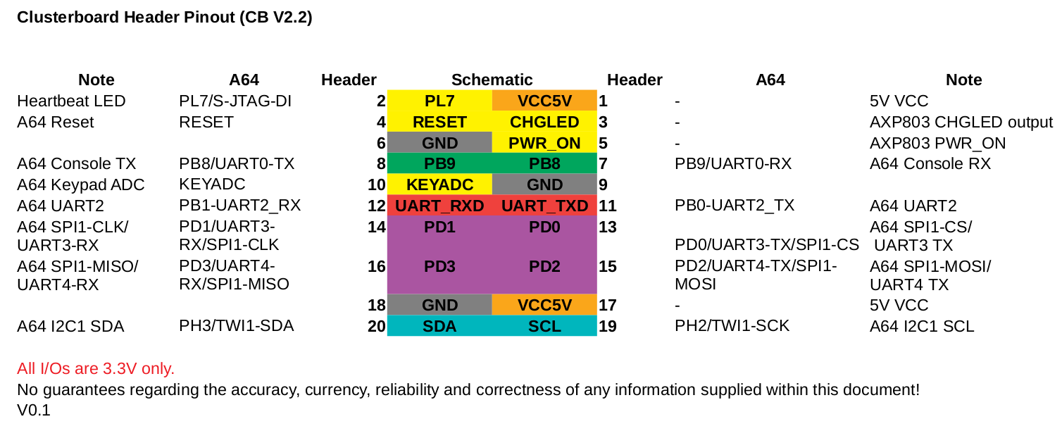
20-pin Expansion Connector
The 20-pin expansion connector is the part J decribed in the section above, available for each SOPINE or SOEDGE module. There is an unofficial description of the pinout in this forum thread. The unofficial pinout is also visible directly in this picture.
SOPINE Module

| Label | Description |
|---|---|
| A | A64 SoC |
| B | 2 GB of DDR3 RAM |
| C | AXP803 PMIC |
| D | Edge connector, the same as on SO-DIMM modules |
| E | microSD card slot |
| F (not annotated yet) | Power LED |
Accessories
- To operate this board you will need a power supply, Pine advises a "5V 15A power supply with 6.3mm OD/3.0mm ID barrel type DC Jack" which is also available in the store (EU/US versions). There are other ways to power this board, but they are not described here yet.
- The board works best when it is protected by a (mITX)case, and has some airflow provided by a fan.
- Each SOPINE module can use cooling, both by a casefan, and by using heatsinks on the individual modules. At least the A64 could use some cooling.
- The first slot can use a eMMC module, which are in the store in 16GB/32GB/64GB/128GB sizes. The modules can be used as a USB stick using a USB adapter. (The eMMC is also readable with the Hardkernel eMMC to microSD converter.)
- Two AA batteries, to allow the SOPINE nodes to retain the RTC (Real Time Clock) time and date information when the power is disconnected.
Installation
To install a cluster it is important to know the IP addresses of each module, so the remote login sessions do not get mixed up.
Each module may be plugged into the Clusterboard individually or consecutively, which makes it easy to assign a hostname to each module separately. It is also possible to manually edit the hostname in the OS image of each module before the first boot.
Serial console
To boot use the serial console connect the pins to UART0 on the GPIO header and connect using baud 115200
- Pin 6: GND
- Pin 7: RTX
- Pin 8: TXD
The pinouts are available in this forum thread.
Operating systems
Armbian
To get the cluster running, start off with a basic Armbian SOPINE install on the first module or directly on all the modules. Armbian offers Debian and Ubuntu as options for download.
There is an issue recognizing the network that needs you to make a change to the base image described here, and a PXE issue. If you have a good description, please add it here. The network issue has been resolved in Armbian builds post December 2020 - as described here.
As of February 2021 the current armbian image is not working (see the post on the arbian forum). The latest working version is 21.02.1. To update the system, the package 'linux-dtb-current-sunxi64' needs to be held back by running
echo "linux-dtb-current-sunxi64 hold" | sudo dpkg --set-selections
There are a number of possible basic installation methods.
- Full install on each module's mSD card.
- eMMC install on the first module.
- PXE boot for all modules, from the first module, or an external host.
Others
The current version of NetBSD may have the networking issue solved in Armbian, as described above.
Frequently asked questions
Q: Are the individual MAC addresses linked to the PHY chips, or the module?
A: The MAC address is specific to the SOPINE module; swapping modules within the Clusterboard does not change the MAC address of the module.
Q: Why will SOPINE modules not reboot when installed on a Clusterboard, but will when installed on a SOPINE Baseboard?
A: The cause has been determined to be back-EMF, and can be resolved with some relatively easy hardware modifications, thanks to excellent troubleshooting performed by Eric. Please, have a look at the extensive article he wrote to find out how to resolve this issue. See also this forum thread for further information.
Q: Do I need heatsinks on any of the components on the Clusterboard?
A: According to the datasheets for the RTL8370N switch ASIC and the RTL8211E PHYs, they consume and thus dissipate up to about 3 W each. As a result, it would be advisable to properly affix passive aluminum heatsinks onto each of these components. Please note that this explanation does not cover the SOPINE and SOEDGE modules.
Schematics and other
- Clusterboard version 2.2 Schematic Capture source file
- Clusterboard version 2.2 Schematic Capture PDF file
- Clusterboard version 2.2 PCB Job source file
- Clusterboard version 2.2 PCB Gerber file
- Clusterboard version 2.2 PCB Layout PDF file
- Clusterboard 20pins header definition
- Clusterboard 3D drawing in Fusion360
- Clusterboard PDF drawing
Hardware revisions
As of April 2021, current revision of the Clusterboard is 2.3; compared with the previous revision, 2.2, it removes the PCB components required for using lithium-polymer batteries for powering each of the modules. Besides the 2.2 revision, there was also an early revision (TO-DO: which exactly?) that required a hardware fix for the eMMC module to work properly.
Links
- https://www.pine64.org/clusterboard/ Clusterboard Introduction
- https://www.pine64.org/sopine/ SOPINE Introduction
- https://pine64.com/product/clusterboard-with-7-sopine-compute-module-slots/ Store page for Clusterboard
- https://pine64.com/product/sopine-a64-compute-module/ Store page for SOPINE module
- https://www.pine64.org/2020/02/03/fosdem-2020-and-hardware-announcements/ Mention of "Clusterboard with 4 SOEDGE and 3 SOPINE modules"
- https://www.pine64.org/2019/08/05/august-update-london-meetup-pinetab-news-soedge-and-more/ SOEDGE Introduction