Difference between revisions of "PineTime"
Panky-codes (talk | contribs) (Added link to the stopwatch article) |
(Add link to DevKit Wiring page because it's quite important) |
||
| (20 intermediate revisions by 10 users not shown) | |||
| Line 1: | Line 1: | ||
== Frequently asked questions == | [[File:Pinetime.png|400px|thumb|right|The PineTime]] | ||
The '''PineTime''' is a free and open source smartwatch capable of running custom-built open operating systems. Some of the notable features include a heart rate monitor, a week-long battery, and a capacitive touch IPS display that is legible in direct sunlight. It is a fully community driven side-project which anyone can contribute to, allowing you to keep control of your device. | |||
== Frequently asked questions / Getting started == | |||
'''Read these first!''' | '''Read these first!''' | ||
* [[PineTime FAQ| Frequently Asked Questions about the | * [[Upgrade PineTime to InfiniTime 1.0.0|Upgrading your new PineTime to InfiniTime 1.0.0]] | ||
* [[PineTime FAQ| Frequently Asked Questions about the PineTime]] | |||
* [[PineTime Devkit Wiring]] | |||
* [[Reprogramming the PineTime|Reprogramming the PineTime (development kit)]] | * [[Reprogramming the PineTime|Reprogramming the PineTime (development kit)]] | ||
* [[Switching your PineTime between InfiniTime and Wasp-os]] | |||
== Default OS == | == Default OS == | ||
| Line 12: | Line 19: | ||
You can find a list of available firmware and other software here: [[PineTime Development]] | You can find a list of available firmware and other software here: [[PineTime Development]] | ||
== Short overview == | == Companion Apps == | ||
PineTime/InfiniTime needs a companion app to e.g. upload a firmware, get notifications from a phone, or just get the date/time. | |||
Here are some companion apps: | |||
* [https://www.gadgetbridge.org Gadgetbridge] (Android >= 4.4) - Companion mobile app, supports updating firmware/bootloader, send notifications, etc. | |||
* [https://openrepos.net/content/piggz/amazfish Amazfish] (SailfishOS and Linux) - Companion mobile and desktop app, supports updating firmware/bootloader, send notifications, etc. | |||
* [https://github.com/alexr4535/siglo Siglo] (Linux) - Companion desktop app. | |||
* [https://github.com/ZephyrLabs/PinetimeFlasher PinetimeFlasher] (Windows) - Companion desktop app, only supports flashing firmware. | |||
* [https://apps.apple.com/us/app/nrf-connect-for-mobile/id1054362403 nRFConnect] (iOS) - Only supports flashing firmware. | |||
* [https://github.com/xan-m/Infini-iOS Infini-iOS] (iOS) - Companion mobile app in early development which will support updating firmware/bootloader, send notifications, etc. | |||
== Short overview / Specifications == | |||
'''Dimensions:''' 37.5 x 40 x 11mm <br> | '''Dimensions:''' 37.5 x 40 x 11mm <br> | ||
'''Weight:''' 38 grams <br> | '''Weight:''' 38 grams <br> | ||
| Line 27: | Line 46: | ||
'''Sensors:''' Accelerometer, Heart rate sensor <br> | '''Sensors:''' Accelerometer, Heart rate sensor <br> | ||
'''Feedback:''' Vibration motor <br> | '''Feedback:''' Vibration motor <br> | ||
'''Battery:''' 170-180mAh LiPo | '''Battery:''' 170-180mAh 3.8V LiPo | ||
= Community = | = Community = | ||
| Line 44: | Line 63: | ||
* [https://t.me/pinetime_dev Telegram group] | * [https://t.me/pinetime_dev Telegram group] | ||
* [https://discordapp.com/invite/DgB7kzr Discord server invite link] | * [https://discordapp.com/invite/DgB7kzr Discord server invite link] | ||
== Development efforts == | == Development efforts == | ||
| Line 55: | Line 73: | ||
* [https://www.ncartron.org/one-week-with-my-pinetime---a-feedback.html Using the PineTime in production (January 2021)] | * [https://www.ncartron.org/one-week-with-my-pinetime---a-feedback.html Using the PineTime in production (January 2021)] | ||
* [https://lupyuen.github.io/articles/sneak-peek-of-pinetime-smart-watch-and-why-its-perfect-for-teaching-iot Sneak Peek of PineTime Smart Watch… And why it’s perfect for teaching IoT] | |||
* [https:// | * [https://lupyuen.github.io/articles/building-a-rust-driver-for-pinetimes-touch-controller Building a Rust Driver for PineTime’s Touch Controller] | ||
* [https://lupyuen.github.io/articles/porting-druid-rust-widgets-to-pinetime-smart-watch Porting (druid) Rust Widgets to PineTime Smart Watch] | |||
* [https:// | * [https://lupyuen.github.io/articles/optimising-pinetimes-display-driver-with-rust-and-mynewt Optimising PineTime’s Display Driver with Rust and Mynewt] | ||
* [https:// | |||
* [https:// | |||
* [https://electronut.in/getting-started-with-zephyr-rtos-on-nordic-nrf52832-hackable/ Getting Started with Zephyr RTOS on Nordic nRF52832 hackaBLE] | * [https://electronut.in/getting-started-with-zephyr-rtos-on-nordic-nrf52832-hackable/ Getting Started with Zephyr RTOS on Nordic nRF52832 hackaBLE] | ||
* [https://blog.aegrel.ee/absniffer-cmsis-dap-sniffer.html Removing the lock and installing another firmware on the nRF52832 using CMSIS-DAP dongle on Linux] | * [https://blog.aegrel.ee/absniffer-cmsis-dap-sniffer.html Removing the lock and installing another firmware on the nRF52832 using CMSIS-DAP dongle on Linux] | ||
* [https://github.com/JF002/nrf52-baseproject/wiki/Build,-program-and-debug-NRF52-project-with-JLink,-CMake-and-CLion Build, program and debug NRF52 project with JLink, CMake and CLion] | * [https://github.com/JF002/nrf52-baseproject/wiki/Build,-program-and-debug-NRF52-project-with-JLink,-CMake-and-CLion Build, program and debug NRF52 project with JLink, CMake and CLion] | ||
* [https://www.nrbtech.io/blog/2020/1/4/using-clion-for-nordic-nrf52-projects Using CLion for Nordic nRF52 projects] | * [https://www.nrbtech.io/blog/2020/1/4/using-clion-for-nordic-nrf52-projects Using CLion for Nordic nRF52 projects] | ||
* [https://dev.to/aaronc81/flashing-your-pinetime-using-an-st-link-and-openocd-54dd Flashing your PineTime using an ST-Link and OpenOCD] | * [https://dev.to/aaronc81/flashing-your-pinetime-using-an-st-link-and-openocd-54dd Flashing your PineTime using an ST-Link and OpenOCD] | ||
* [https://zephyrlabs.github.io/Watchfaces/ Zephyrlabs: just a bunch of watchfaces made for the pinetime] | * [https://zephyrlabs.github.io/Watchfaces/ Zephyrlabs: just a bunch of watchfaces made for the pinetime] | ||
* [https://pankajraghav.com/2021/04/03/PINETIME-STOPCLOCK.html Creating a stopwatch in Pinetime (with Infinitime)] | |||
= Hardware = | |||
== Display == | |||
Note: The factory-default software on the PineTime does not auto-detect the display being disconnected when it has already booted. That can cause garbled output, to fix it just restart the PineTime. | Note: The factory-default software on the PineTime does not auto-detect the display being disconnected when it has already booted. That can cause garbled output, to fix it just restart the PineTime. | ||
| Line 121: | Line 128: | ||
[https://github.com/adafruit/Adafruit-ST7735-Library/ Adafruit ST7789 driver in cpp] | [https://github.com/adafruit/Adafruit-ST7735-Library/ Adafruit ST7789 driver in cpp] | ||
== Battery measurement == | |||
Reading whether the PineTime has power attached is easy: simply read the charge indication pin (P0.12). When it is high it is running on battery, when it is low it is charging. | Reading whether the PineTime has power attached is easy: simply read the charge indication pin (P0.12). When it is high it is running on battery, when it is low it is charging. | ||
| Line 140: | Line 147: | ||
Converting this voltage to an estimated capacity in percent requires a more complicated algorithm, because Lithium-ion batteries have a non-linear discharge curve. | Converting this voltage to an estimated capacity in percent requires a more complicated algorithm, because Lithium-ion batteries have a non-linear discharge curve. | ||
== Button == | |||
The button on the side of the PineTime is disabled by default. To enable it, drive the button out pin (P0.15) high. | The button on the side of the PineTime is disabled by default. To enable it, drive the button out pin (P0.15) high. | ||
| Line 147: | Line 153: | ||
While enabled, the button in pin (P0.13) will be high when the button is pressed, and low when it is not pressed. | While enabled, the button in pin (P0.13) will be high when the button is pressed, and low when it is not pressed. | ||
== Touch panel == | |||
The touch panel is controlled by a Hynitron CST816S chips. Unfortunately, there is not much information about this chip on the internet apart from the datasheet below and a [https://github.com/lupyuen/hynitron_i2c_cst0xxse/ reference driver]. This is enough to implement a basic driver, but crucial information needed to implement advanced functionalities are missing (I²C protocol and registers, timings, power modes,...). | The touch panel is controlled by a Hynitron CST816S chips. Unfortunately, there is not much information about this chip on the internet apart from the datasheet below and a [https://github.com/lupyuen/hynitron_i2c_cst0xxse/ reference driver]. This is enough to implement a basic driver, but crucial information needed to implement advanced functionalities are missing (I²C protocol and registers, timings, power modes,...). | ||
=== Pins === | |||
* P0.10 : Reset | * P0.10 : Reset | ||
| Line 158: | Line 164: | ||
* P0.07 : I²C SCL | * P0.07 : I²C SCL | ||
=== I²C === | |||
* Device address : 0x15 | * Device address : 0x15 | ||
* Frequency : from 10Khz to 400Khz | * Frequency : from 10Khz to 400Khz | ||
'''NOTE : ''' The controller go to sleep when no event is detected. In sleep mode, the controller does not communicate on the I²C bus (it appears disconnected). So, for the communication to work, you need to tap on the screen so that the chip wakes-up. | '''NOTE: ''' The controller go to sleep when no event is detected. In sleep mode, the controller does not communicate on the I²C bus (it appears disconnected). So, for the communication to work, you need to tap on the screen so that the chip wakes-up. | ||
'''NOTE: ''' The I²C bus, also known as TWI bus has known issues, make sure to write your TWI driver with timeouts. | |||
=== Touch events === | |||
Touch information is available from the 63 first registers of the controller. Remember: the device is in sleep mode when no touch event is detected. It means that you can read the register only when the touch controller detected an event. You can use the ''Interrupt'' pin to detect such event in the software. | Touch information is available from the 63 first registers of the controller. Remember: the device is in sleep mode when no touch event is detected. It means that you can read the register only when the touch controller detected an event. You can use the ''Interrupt'' pin to detect such event in the software. | ||
| Line 238: | Line 246: | ||
* Fields X, Y, Number of touch points and touch ID are updated. The others are always 0. | * Fields X, Y, Number of touch points and touch ID are updated. The others are always 0. | ||
=== Registers === | |||
The reference driver specifies some registers and value, but there is no information about them: | The reference driver specifies some registers and value, but there is no information about them: | ||
| Line 314: | Line 322: | ||
'''WARNING : ''' <del>Writing the SLEEP command (write 0x05 in HYN_REG_POWER_MODE) seems to freeze the controller (it returns only static values) until the battery is totally drained and the whole system reset. Analysis and debugging is more than welcome!</del> | '''WARNING : ''' <del>Writing the SLEEP command (write 0x05 in HYN_REG_POWER_MODE) seems to freeze the controller (it returns only static values) until the battery is totally drained and the whole system reset. Analysis and debugging is more than welcome!</del> | ||
==Accelerometer== | |||
The on board accelerometer is Bosch BMA421, connected to the I2C bus. | The on board accelerometer is Bosch BMA421, connected to the I2C bus. | ||
=== Pins === | |||
* P0.06 : I²C SDA | * P0.06 : I²C SDA | ||
| Line 326: | Line 333: | ||
I2C Device address : 0x18 | I2C Device address : 0x18 | ||
= Datasheets and Schematics = | |||
== | == Schematics == | ||
* [https://files.pine64.org/doc/PineTime/PineTime%20Schematic-V1.0a-20191103.pdf PineTime Schematic ver1.0a] | * [https://files.pine64.org/doc/PineTime/PineTime%20Schematic-V1.0a-20191103.pdf PineTime Schematic ver1.0a] | ||
* [https://files.pine64.org/doc/PineTime/PineTime%20Port%20Assignment%20rev1.0.pdf PineTime GPIO Port Assignment ver1.0] | * [https://files.pine64.org/doc/PineTime/PineTime%20Port%20Assignment%20rev1.0.pdf PineTime GPIO Port Assignment ver1.0] | ||
| Line 335: | Line 341: | ||
Note: The part number for the SPI FLASH in the schematic diagram is not correct, the PineTime features a larger external FLASH device, see below. | Note: The part number for the SPI FLASH in the schematic diagram is not correct, the PineTime features a larger external FLASH device, see below. | ||
== Chip Datasheets == | |||
* NORDIC nRF52832 information: | * NORDIC nRF52832 information: | ||
** [https://files.pine64.org/doc/datasheet/pinetime/nRF52832%20product%20brief.pdf nRF52832 Product Brief] | ** [https://files.pine64.org/doc/datasheet/pinetime/nRF52832%20product%20brief.pdf nRF52832 Product Brief] | ||
** [https://infocenter.nordicsemi.com/pdf/nRF52832_PS_v1. | ** [https://infocenter.nordicsemi.com/pdf/nRF52832_PS_v1.4.pdf nRF52832 Product Specification v1.4] | ||
* ARMv7-M information: | * ARMv7-M information: | ||
** [https://static.docs.arm.com/ddi0403/eb/DDI0403E_B_armv7m_arm.pdf ARMv7-M Architecture Reference Manual] | ** [https://static.docs.arm.com/ddi0403/eb/DDI0403E_B_armv7m_arm.pdf ARMv7-M Architecture Reference Manual] | ||
== Component Datasheets == | |||
* PMU (Power Management Unit) information: | * PMU (Power Management Unit) information: | ||
** [https://files.pine64.org/doc/datasheet/pinetime/SGM40561.pdf SGMicro SGM40561 Single Cell Charger Datasheet] | ** [https://files.pine64.org/doc/datasheet/pinetime/SGM40561.pdf SGMicro SGM40561 Single Cell Charger Datasheet] | ||
| Line 362: | Line 368: | ||
** [https://files.pine64.org/doc/datasheet/pinetime/HRS3300%20Heart%20Rate%20Sensor.pdf TianYiHeXin HRS3300 PPG Heart Rate Sensor Data Sheet] | ** [https://files.pine64.org/doc/datasheet/pinetime/HRS3300%20Heart%20Rate%20Sensor.pdf TianYiHeXin HRS3300 PPG Heart Rate Sensor Data Sheet] | ||
= Community case design = | |||
* [https://www.thingiverse.com/thing:4172849 PineTime Smart Watch case by dara0s at thingiverse] | |||
* [https://www.thingiverse.com/thing:4651462 PineTime dev kit back fix by joaquimorg at thingiverse] | |||
* [https://www.thingiverse.com/thing:4172849 PineTime Smart Watch case at | * [https://www.thingiverse.com/thing:4763267 PineTime dev kit charging holder v4 by zevix81 at thingiverse] | ||
* [https://www.thingiverse.com/thing:4651462 PineTime dev kit back fix at | |||
* [https://www.thingiverse.com/thing:4763267 PineTime dev kit charging holder v4 by zevix81] | |||
[[Category:PineTime]] | [[Category:PineTime]] | ||
Revision as of 22:44, 17 September 2021

The PineTime is a free and open source smartwatch capable of running custom-built open operating systems. Some of the notable features include a heart rate monitor, a week-long battery, and a capacitive touch IPS display that is legible in direct sunlight. It is a fully community driven side-project which anyone can contribute to, allowing you to keep control of your device.
Frequently asked questions / Getting started
Read these first!
- Upgrading your new PineTime to InfiniTime 1.0.0
- Frequently Asked Questions about the PineTime
- PineTime Devkit Wiring
- Reprogramming the PineTime (development kit)
- Switching your PineTime between InfiniTime and Wasp-os
Default OS
The current default operating system on the PineTime is called InfiniTime, you can find more information about the firmware on its GitHub page. First devkits shipped with a proprietary custom firmware.
You can find a list of available firmware and other software here: PineTime Development
Companion Apps
PineTime/InfiniTime needs a companion app to e.g. upload a firmware, get notifications from a phone, or just get the date/time. Here are some companion apps:
- Gadgetbridge (Android >= 4.4) - Companion mobile app, supports updating firmware/bootloader, send notifications, etc.
- Amazfish (SailfishOS and Linux) - Companion mobile and desktop app, supports updating firmware/bootloader, send notifications, etc.
- Siglo (Linux) - Companion desktop app.
- PinetimeFlasher (Windows) - Companion desktop app, only supports flashing firmware.
- nRFConnect (iOS) - Only supports flashing firmware.
- Infini-iOS (iOS) - Companion mobile app in early development which will support updating firmware/bootloader, send notifications, etc.
Short overview / Specifications
Dimensions: 37.5 x 40 x 11mm
Weight: 38 grams
IP Rating: IP67 (waterproof to 1 meter (sealed edition!))
Display:
- Size: 1.3 inches (33mm) diagonal
- Type: IPS capacitive touchscreen, RGB 65K colors
- Display Controller: ST7789
- Resolution: 240x240 pixels
System on Chip: Nordic Semiconductor nRF52832
Flash: 512KB with additional 4MB SPI NOR
RAM: 64KB
Bluetooth: 5.0 (including Bluetooth Low Energy)
Sensors: Accelerometer, Heart rate sensor
Feedback: Vibration motor
Battery: 170-180mAh 3.8V LiPo
Community
Forum
Chat
- Matrix Channel (No login required to read)
- IRC Server: irc.pine64.org Channel: PineTime
- Telegram group
- Discord server invite link
Developers and coding
- Matrix Channel (No login required to read)
- Telegram group
- Discord server invite link
Development efforts
To read more about development on the PineTime, the projects available and more technical details, check out PineTime Development
Useful articles and blog posts
If you want to dive in to the ecosystem, here's a short list of various articles and blog posts that can help you set up your soft- or hardware development environment.
- Using the PineTime in production (January 2021)
- Sneak Peek of PineTime Smart Watch… And why it’s perfect for teaching IoT
- Building a Rust Driver for PineTime’s Touch Controller
- Porting (druid) Rust Widgets to PineTime Smart Watch
- Optimising PineTime’s Display Driver with Rust and Mynewt
- Getting Started with Zephyr RTOS on Nordic nRF52832 hackaBLE
- Removing the lock and installing another firmware on the nRF52832 using CMSIS-DAP dongle on Linux
- Build, program and debug NRF52 project with JLink, CMake and CLion
- Using CLion for Nordic nRF52 projects
- Flashing your PineTime using an ST-Link and OpenOCD
- Zephyrlabs: just a bunch of watchfaces made for the pinetime
- Creating a stopwatch in Pinetime (with Infinitime)
Hardware
Display
Note: The factory-default software on the PineTime does not auto-detect the display being disconnected when it has already booted. That can cause garbled output, to fix it just restart the PineTime.
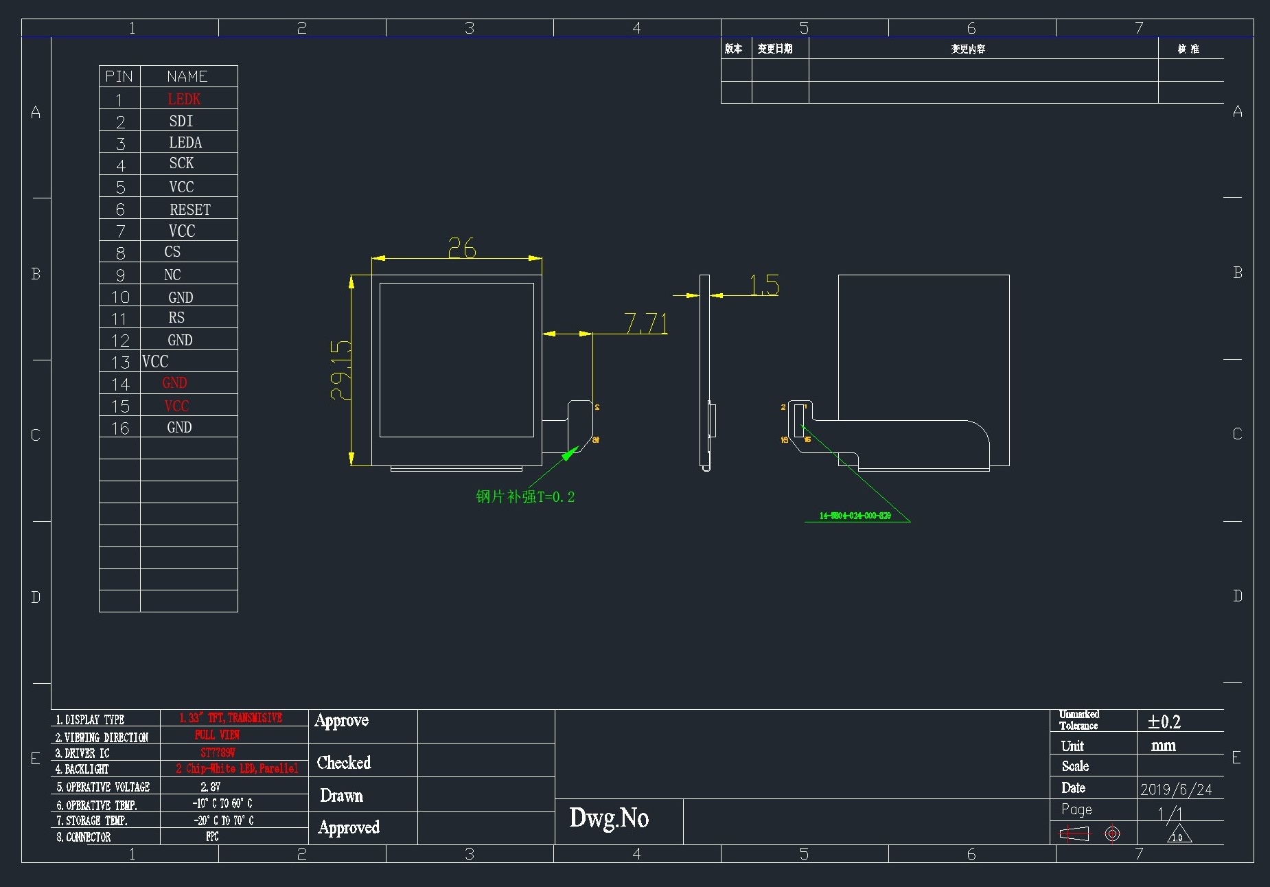
The display is driven using the ST7789 display controller. Use the following pins to drive the screen:
| PineTime pin | ST7789 pin |
|---|---|
| LCD_SCK (P0.02) | SPI clock |
| LCD_SDI (P0.03) | SPI MOSI |
| LCD_RS (P0.18) | Command/Data pin (CD) |
| LCD_CS (P0.25) | Chip select |
| LCD_RESET (P0.26) | Display reset |
| LCD_BACKLIGHT_{LOW,MID,HIGH} | Backlight (active low) |
Notes:
- Chip select must be held low while driving the display. It must be high when using other SPI devices on the same bus (such as external flash storage) so that the display controller won't respond to the wrong commands.
- SPI must be used in mode 3. Mode 0 (the default) won't work.
- LCD_DISPLAY_* is used to enable the backlight. Set at least one to low to see anything on the screen.
- Use SPI at 8MHz (the fastest clock available on the nRF52832) because otherwise refreshing will be super slow.
References:
Battery measurement
Reading whether the PineTime has power attached is easy: simply read the charge indication pin (P0.12). When it is high it is running on battery, when it is low it is charging.
Reading the battery voltage is a bit harder. For that you can use the battery voltage pin on P0.31 (AIN7). The returned value is 12 bits, which means it is 0..4095. You can get the measured voltage with the following formula, assuming a reference voltage of 3.3V (this is configurable in the ADC):
adcVoltage = adcValue / (4095 / 3.3)
The measured voltage is actually half of the actual battery voltage, because the ADC is connected between a voltage divider where both resistors are 1MΩ. This can be corrected by multiplying the value:
batteryVoltage = adcValue * 2 / (4095 / 3.3)
It's often better to avoid floating point values on embedded systems and in this case there is no reason to use float at all, we can just represent the value in millivolts. Therefore the formula can be simplified to:
batteryVoltage = adcValue * 2000 / (4095 / 3.3)
batteryVoltage = adcValue * 2000 / 1241
Converting this voltage to an estimated capacity in percent requires a more complicated algorithm, because Lithium-ion batteries have a non-linear discharge curve.
Button
The button on the side of the PineTime is disabled by default. To enable it, drive the button out pin (P0.15) high.
While enabled, the button in pin (P0.13) will be high when the button is pressed, and low when it is not pressed.
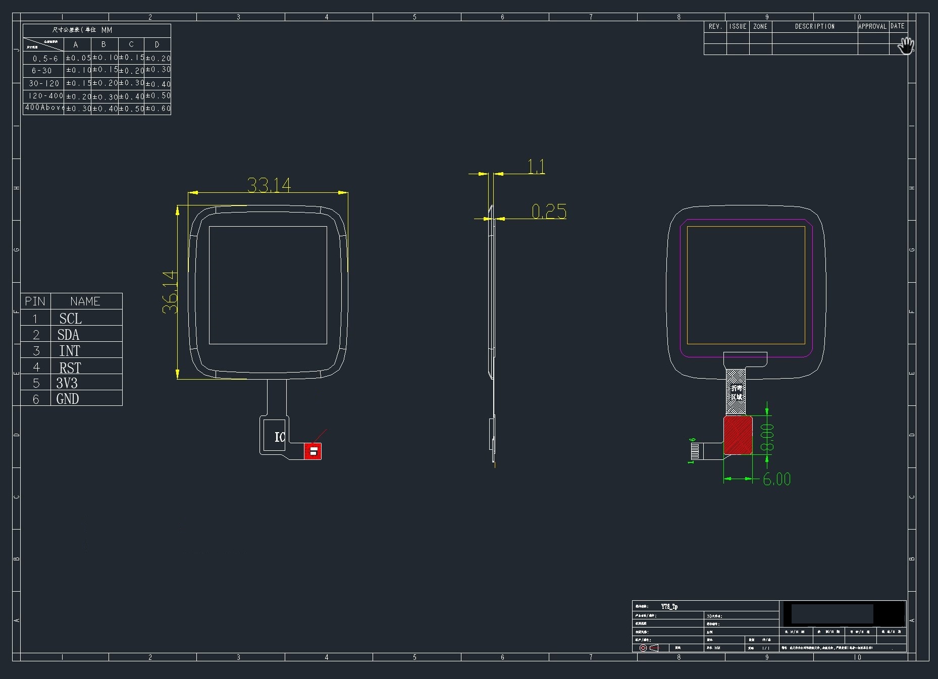
Touch panel
The touch panel is controlled by a Hynitron CST816S chips. Unfortunately, there is not much information about this chip on the internet apart from the datasheet below and a reference driver. This is enough to implement a basic driver, but crucial information needed to implement advanced functionalities are missing (I²C protocol and registers, timings, power modes,...).
Pins
- P0.10 : Reset
- P0.28 : Interrupt (signal to the CPU when a touch event is detected)
- P0.06 : I²C SDA
- P0.07 : I²C SCL
I²C
- Device address : 0x15
- Frequency : from 10Khz to 400Khz
NOTE: The controller go to sleep when no event is detected. In sleep mode, the controller does not communicate on the I²C bus (it appears disconnected). So, for the communication to work, you need to tap on the screen so that the chip wakes-up.
NOTE: The I²C bus, also known as TWI bus has known issues, make sure to write your TWI driver with timeouts.
Touch events
Touch information is available from the 63 first registers of the controller. Remember: the device is in sleep mode when no touch event is detected. It means that you can read the register only when the touch controller detected an event. You can use the Interrupt pin to detect such event in the software.
These 63 bytes contain up to 10 touch point (X, Y, event type, pressure,...) :
| Byte | Bit7 | Bit6 | Bit5 | Bit4 | Bit3 | Bit2 | Bit1 | Bit0 |
|---|---|---|---|---|---|---|---|---|
| 0 | ? | |||||||
| 1 | GestureID : (Gesture code ,
0x00: no gesture, 0x01: Slide down, 0x02: Slide up, 0x03: Slide left, 0x04: Slide right, 0x05: Single click, 0x0B: Double click, 0x0C: Long press) | |||||||
| 2 | ? | Number of touch points | ||||||
| 3 | Event (0 = Down, 1 = Up, 2 = Contact) | ? | X (MSB) coordinate | |||||
| 4 | X (LSB) coordinate | |||||||
| 5 | ? | Touch ID | Y (MSB) coordinate | |||||
| 6 | Y (LSB) coordinate | |||||||
| 7 | Pressure (?) | |||||||
| 8 | Miscellaneous (?) | |||||||
Bytes 3 to 8 are repeated 10 times (10*6 + 3 = 63 bytes).
NOTES
- The touch controller seems to report only 1 touch point
- Fields X, Y, Number of touch points and touch ID are updated. The others are always 0.
Registers
The reference driver specifies some registers and value, but there is no information about them:
| Register | Address | Description |
|---|---|---|
| HYN_REG_INT_CNT | 0x8F | |
| HYN_REG_FLOW_WORK_CNT | 0x91 | |
| HYN_REG_WORKMODE | 0x00 | 0 = WORK, 0x40 = FACTORY |
| HYN_REG_CHIP_ID | 0xA3 | |
| HYN_REG_CHIP_ID2 | 0x9F | |
| HYN_REG_POWER_MODE | 0xA5 | 0x03 = SLEEP (reset the touchpanel using the reset pin before using this register : pin_low, delay 5ms, pin_high, delay 50ms then write 3 to register 0xA5) |
| HYN_REG_FW_VER | 0xA6 | |
| HYN_REG_VENDOR_ID | 0xA8 | |
| HYN_REG_LCD_BUSY_NUM | 0xAB | |
| HYN_REG_FACE_DEC_MODE_EN | 0xB0 | |
| HYN_REG_GLOVE_MODE_EN | 0xC0 | |
| HYN_REG_COVER_MODE_EN | 0xC1 | |
| HYN_REG_CHARGER_MODE_EN | 0x8B | |
| HYN_REG_GESTURE_EN | 0xD0 | |
| HYN_REG_GESTURE_OUTPUT_ADDRESS | 0xD3 | |
| HYN_REG_ESD_SATURATE 0xED | 0xED |
WARNING : Writing the SLEEP command (write 0x05 in HYN_REG_POWER_MODE) seems to freeze the controller (it returns only static values) until the battery is totally drained and the whole system reset. Analysis and debugging is more than welcome!
Accelerometer
The on board accelerometer is Bosch BMA421, connected to the I2C bus.
Pins
- P0.06 : I²C SDA
- P0.07 : I²C SCL
- P0.08 : Interrupt
I2C Device address : 0x18
Datasheets and Schematics
Schematics
Note: The part number for the SPI FLASH in the schematic diagram is not correct, the PineTime features a larger external FLASH device, see below.
Chip Datasheets
- NORDIC nRF52832 information:
- ARMv7-M information:
Component Datasheets
- PMU (Power Management Unit) information:
- SPI Flash information:
- XTX XT25F32B 32Mb(4MB) SPI NOR Flash (data sheets for this part are hard to find but it acts similar to other QuadSPI SPI NOR Flash such as Macronix 32Mb(4MB) SPI NOR Flash)
- XTX XT25F32B
- IDs for XT25F32B are: manufacturer (0x0b), device (0x15), memory type (0x40), density (0x16)
- LCD Panel:
- Touchpad information:
- Sensor: