Difference between revisions of "Pinebook Pro"
(→Power Supply: Small cleanups and improvements) |
|||
| Line 1,124: | Line 1,124: | ||
* Battery monitoring IC: [https://cdn.datasheetspdf.com/pdf-down/C/W/2/CW2015-Cellwise.pdf Cellwise CW2015 Datasheet] | * Battery monitoring IC: [https://cdn.datasheetspdf.com/pdf-down/C/W/2/CW2015-Cellwise.pdf Cellwise CW2015 Datasheet] | ||
* [https://files.pine64.org/doc/datasheet/pinebook/40110175P%203.8V%2010000mAh规格书-14.pdf 10000 mAh Lithium Battery Specification] | * [https://files.pine64.org/doc/datasheet/pinebook/40110175P%203.8V%2010000mAh规格书-14.pdf 10000 mAh Lithium Battery Specification] | ||
* Later batches | * [https://files.pine64.org/doc/datasheet/pinebook/40110175P%203.8V%209600mAh%20Lithium%20Battery%20Specification Later batches c9600 mAh / 36.48 Wh model WYC40110175P battery specification] | ||
Power path device: | Power path device: | ||
Revision as of 19:07, 18 September 2024
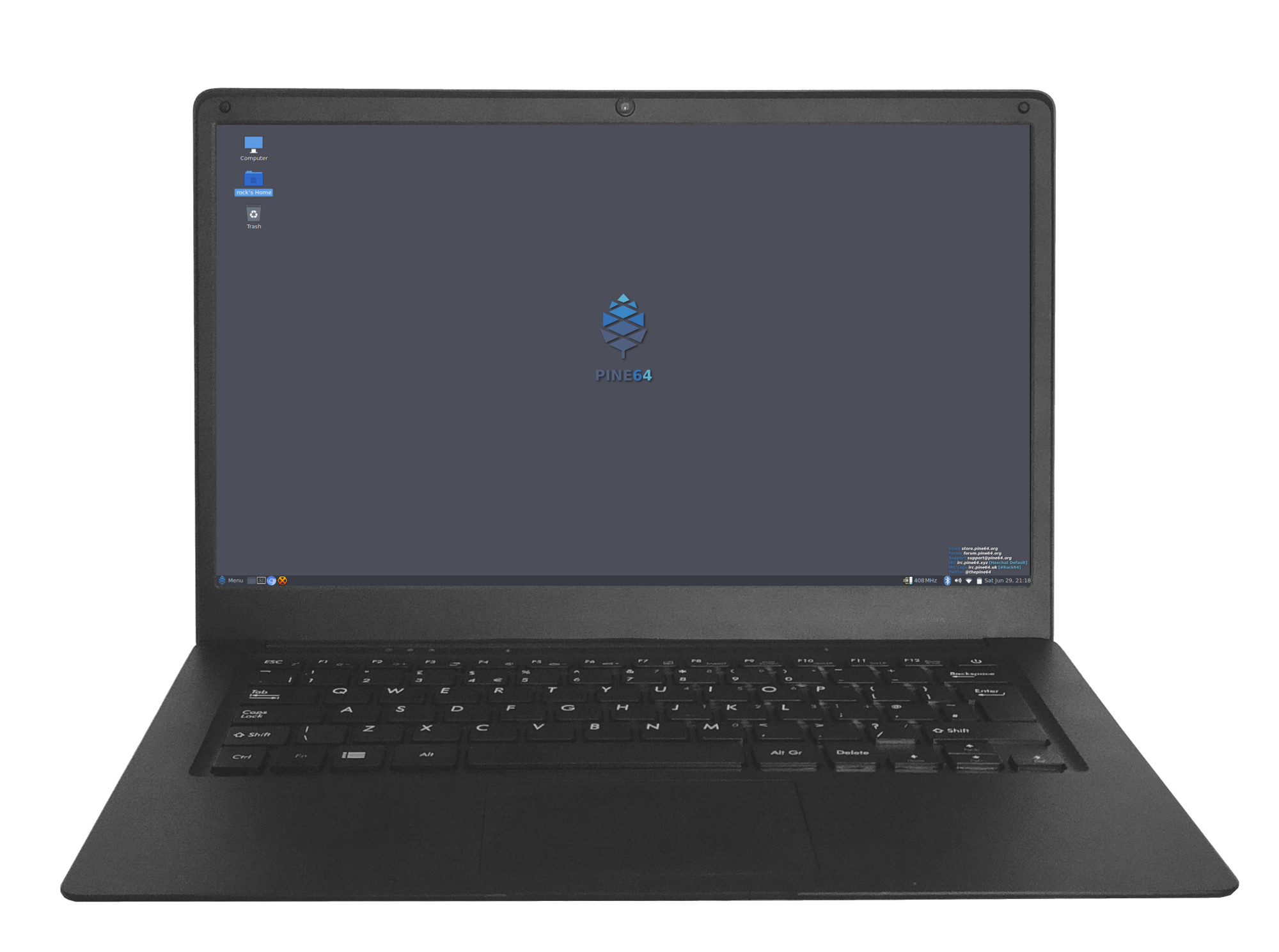
The Pinebook Pro is a Linux and *BSD ARM laptop from PINE64. It is built to be a compelling alternative to mid-ranged Chromebooks that people convert into Linux laptops.
The Pinebook Pro features an IPS 1080p 14″ LCD panel, a premium magnesium alloy shell, high capacity eMMC storage, a 10,000 mAh (9,600 mAh in later batches) capacity battery, and the modularity that only an open source project can deliver with the dimensions of 329mm x 220mm x 12mm (WxDxH). Key features include the Rockchip RK3399 SoC, USB-C for data, video-out and power-in (2.5 A at 5 V), privacy switches for the microphone, BT/WiFi module, camera and expandable storage via NVMe (PCIe x4) with an optional adapter.
The Pinebook Pro is equipped with 4 GB of LPDDR4 system memory, up to 128 GB of eMMC flash storage, and 128 Mbit of SPI boot flash. The I/O includes: 1 x micro SD card reader (bootable), 1 x USB 2.0, 1 x USB 3.0, 1 x USB Type-C host with DP 1.2 and power-in, PCI Express x4 for an M.2 NVMe SSD drive (requires an optional adapter), and serial console UART (via the headphone jack by setting an internal switch). The keyboard and touchpad both use the USB 2.0 protocol. The LCD panel uses the eDP MiPi display protocol.
Software and OS Image Downloads
Many different Operating Systems (OS) are freely available from the open source community and partner projects. These include various flavors of GNU/Linux (Ubuntu, Debian, Manjaro, etc.) and *BSD.
Default Manjaro KDE Desktop Quick Start
When you first get your Pinebook Pro and boot it up for the first time, it'll come with Manjaro using the KDE desktop. The Pinebook Pro is officially supported by the Manjaro ARM project, and support can be found on the Manjaro ARM forums.
On first boot, it will ask for certain information such as your timezone location, keyboard layout, username, password, and hostname. Most of these should be self-explanatory. Note that the hostname it asks for should be thought of as the "codename" of your machine, and if you don't know what it's about, you can make something up (use a single word, all lower case, no punctuation, e.g. "pbpro").
After you're on the desktop, be sure to update it as soon as possible and reboot after updates are finished installing. If nothing appears when you click on the Networking icon in your system tray to connect to your Wi-Fi, ensure the Wi-Fi privacy switch is not disabled.
Pinebook Pro images
Under Pinebook Pro Software Releases you will find a complete list of currently supported Operating System images that work with the Pinebook as well as other related software.
Linux, the kernel, downstream source
Although the current upstream version boots and works, the development of new features and other improvements is still ongoing. The results (including detailed changelogs) are published on megi's tree.
Hardware-accelerated video decoding
Drivers for accelerated video decoding are available in the current kernels but to use the v4l2-request API with FFmpeg (and the apps that depend on it) one needs to build a fork. With mpv built against it and the integrated yt-dlp support watching YouTube and similar sources is possible without stressing the CPU. Read more at Mainline Hardware Decoding.
Keyboard
The Pinebook Pro is available in two keyboard configurations: ISO and ANSI. Both the keyboard and touchpad in the Pinebook Pro use the USB 2.0 protocol and show up as such in xinput. The keyboard features function (Fn) keys in the F-key row, which include display brightness controls, sound volume, touchpad lock, and other functionality. There is also a custom PINE64 logo key that functions as Menu/Super key. It has also a secondary functionality for setting the privacy switches.
The keyboard firmware binary can be flashed from userspace using the provided open source utility.
Documentation for the keyboard can be found in Datasheets for Components and Peripherals and details regarding the assembly can be found under Pinebook Pro Keyboard Assembly.
Typing special characters
The UK ISO Layout does not have dedicated keys for characters like the German umlauts (Ä, Ö, Ü, etc). Certain characters can still be generated by means of either key combinations or key sequences.
| Character | Key combination/sequence |
|---|---|
| Ä, Ö, Ü, ä, ö, ü | [AltGr]+'[' followed by [A], [O], [U], [a], [o] or [u] |
| µ | [AltGr]+[m] |
| Ø, ø | [AltGr]+[O], [AltGr]+[o] |
| @ | [AltGr]+[q] (as on the German layout) |
| ß | [AltGr]+[s] |
| § | [AltGr]+[S] |
| ° | [AltGr]+[)] |
Privacy Switches
There are three privacy switches mapped to the F10, F11 and F12 keys on the Pinebook Pro keyboard. They de/activate the following:
| Combination | Effect | Description | Notes |
|---|---|---|---|
| PINE64 logo key+F10 | Microphone Privacy switch | CAPs lock LED blinks. 2 blinks = enabled, 3 blinks = disabled | |
| PINE64 logo key+F11 | WiFi Privacy switch | NUM lock LED blinks. 2 blinks = WiFi enabled / privacy switch disabled, 3 blinks = WiFi disabled / privacy switch enabled. | Re-enabling requires reboot (or a command line hack to bind/unbind). |
| PINE64 logo key+F12 | Camera privacy switch | CAPs lock and NUM lock LEDs blink together. 2 blinks = enabled, 3 blinks = disabled | Can use tools like lsusb to detect camera's presence. If not detected, check privacy switch.
|
(Press the PINE64 logo key plus F10/F11/F12) for 3 seconds)
The keyboard operates on firmware independent of the operating system. It detects if one of the F10, F11 or F12 keys is pressed in combination with the Pine key for 3 seconds. Doing so disables power to the appropriate peripheral, thereby disabling it. This has the same effect as cutting off the power to each peripheral with a physical switch. This implementation is very secure, since the firmware that determines whether a peripheral gets power is not part of the Pinebook Pro’s operating system. So the power state value for each peripheral cannot be overridden or accessed from the operating system. The power state setting for each peripheral is stored across reboots inside the keyboard's firmware flash memory.
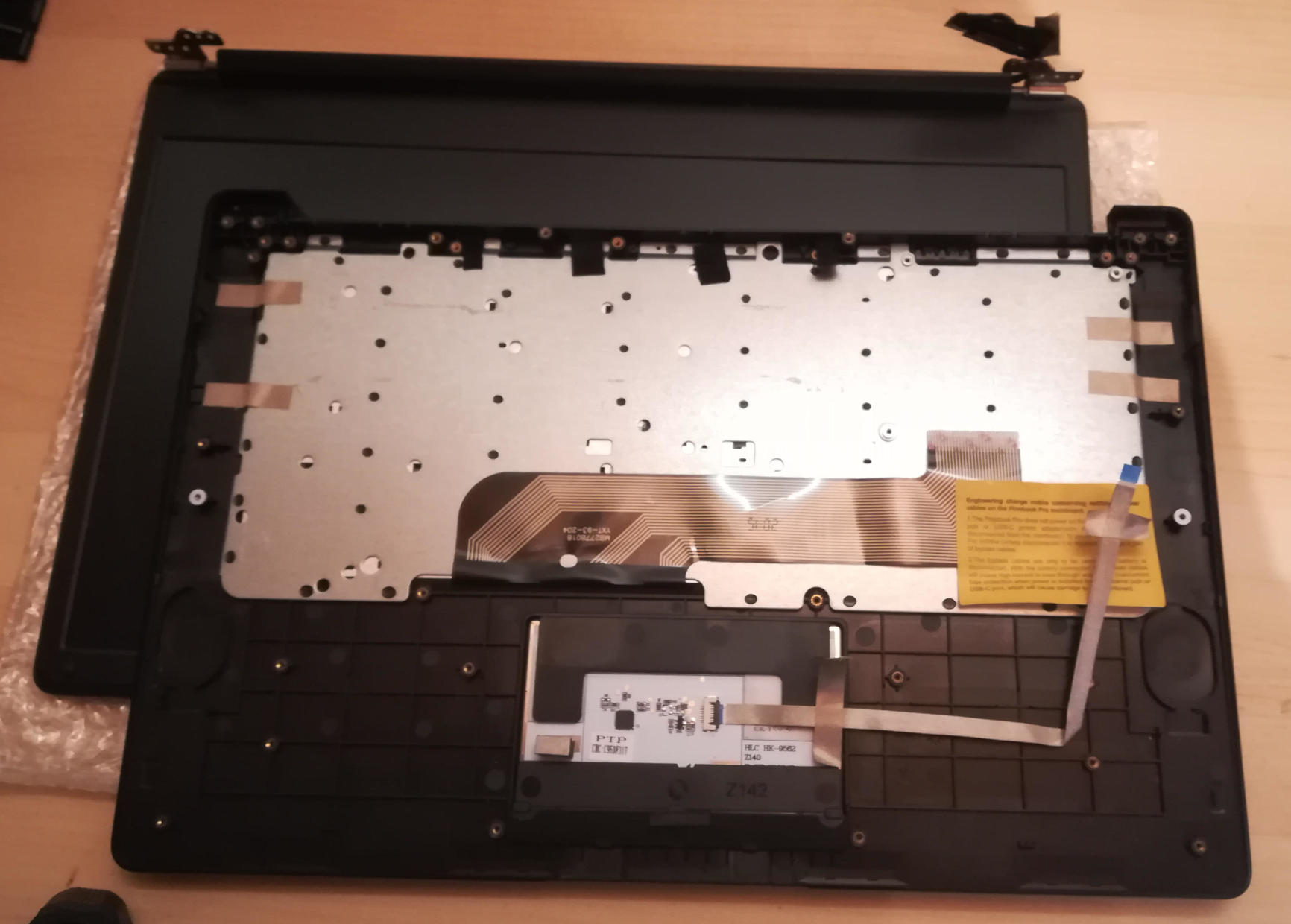
Basic summary of replacing keyboard
This guide is very basic and should be fleshed out with (better) pictures. There just isn't a list of steps anywhere else yet.
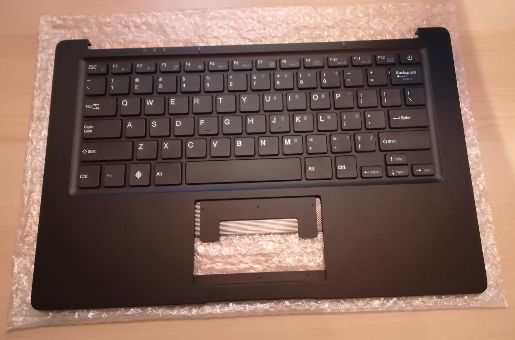
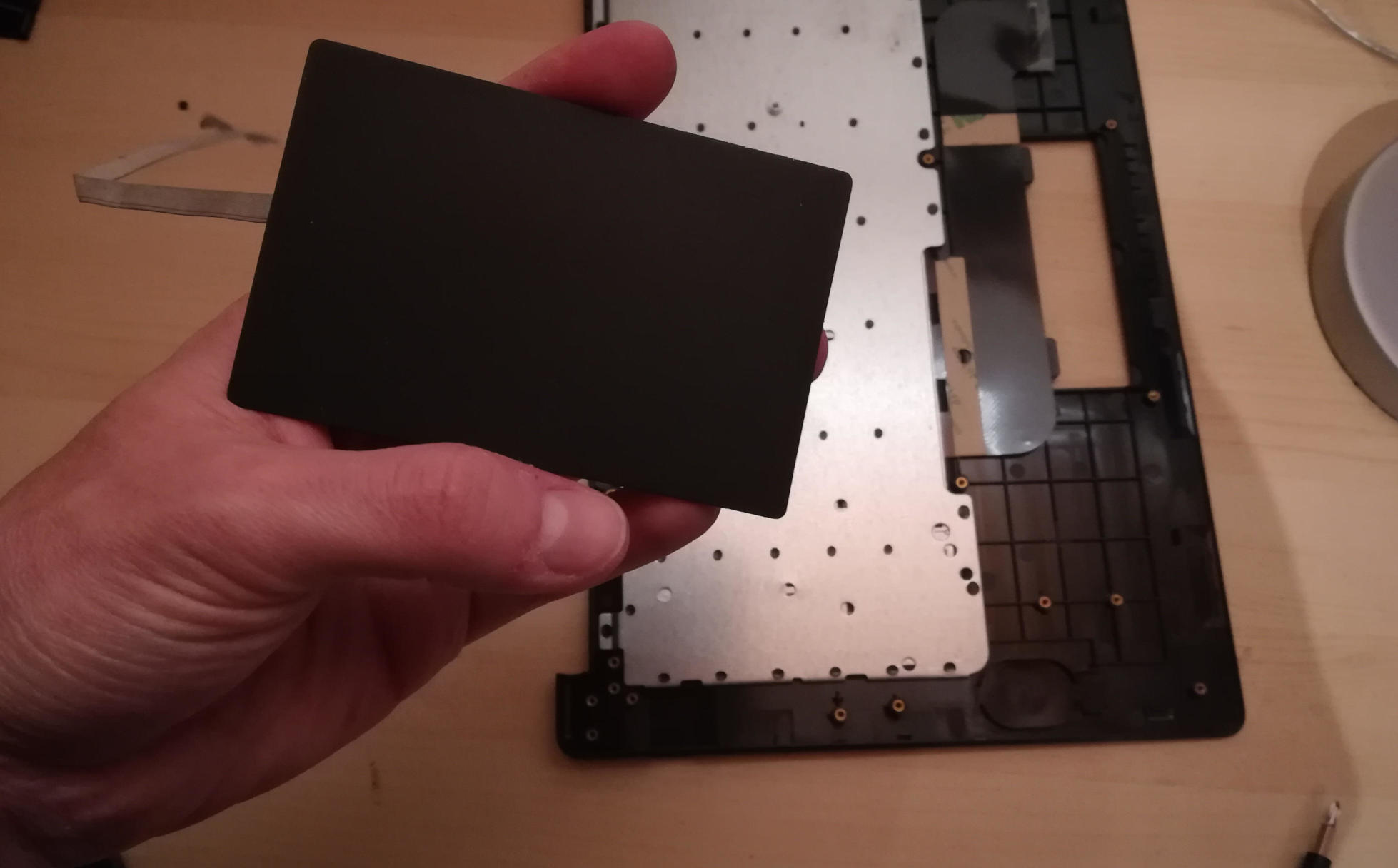
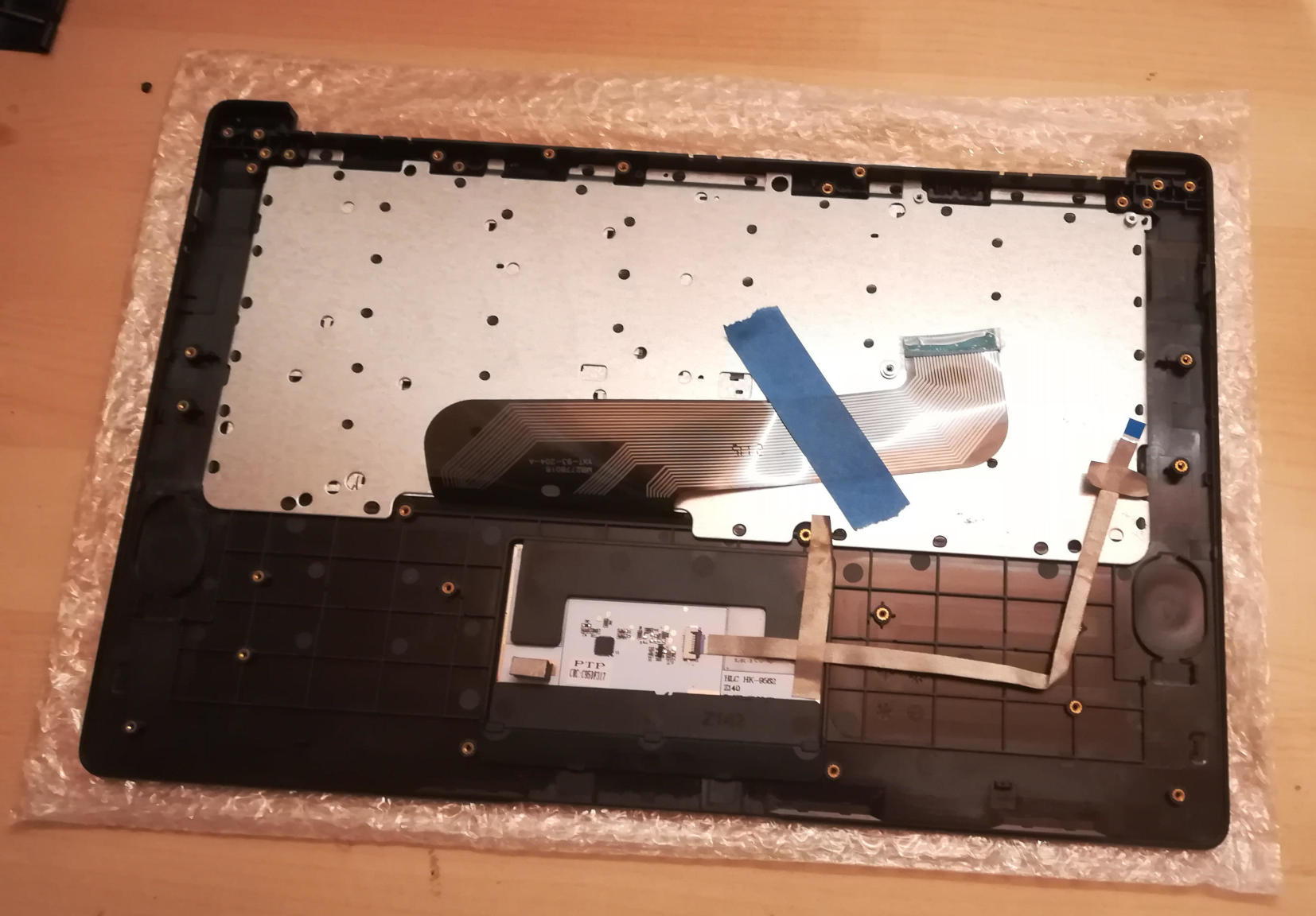
Here's what the replacement keyboard looks like:
Step 0: If changing from ISO keyboard to ANSI keyboard, or vice versa, be sure to have a system capable of running the firmware updater that you can access either remotely or with a USB keyboard beyond the internal keyboard, as the firmware for each is very different and keys won't work correctly. See https://forum.pine64.org/showthread.php?tid=8407 (and for NetBSD, https://forum.pine64.org/showthread.php?tid=8716).
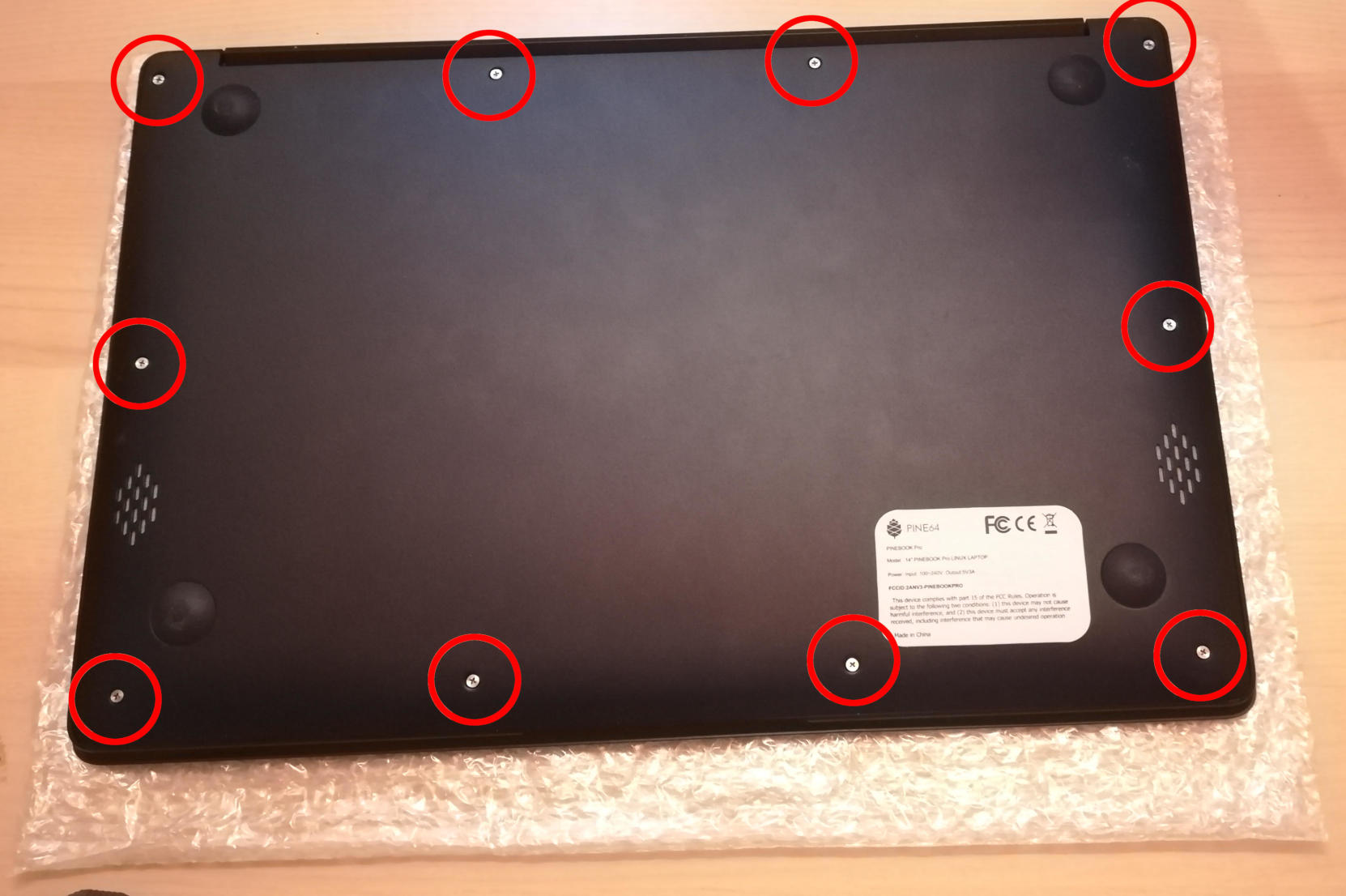
Step 1: The remove back back panel.
There are 10 screws on the back that must be removed, and the back panel detached. I recommend using a PH0 bit. The speakers may remain attached via glue to the case and should be carefully pried off. When this is done, taking photos of how everything looks now can help put it all back together later.
Step 2: Places to unscrew.
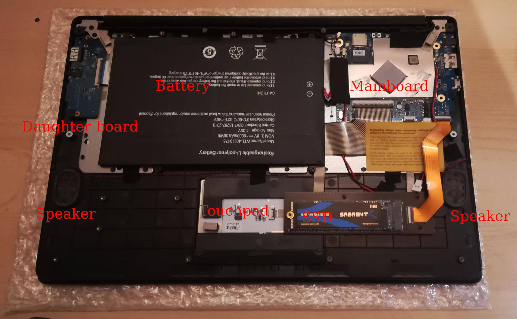
There are 3 items screwed into the keyboard frame that must be removed. There are 2 large screws for daughter board, 3 large screws and 1 small screw for mainboard, and 4 small screws for battery. Be sure to not lose them. I recommend a PH00 bit for the large screws on the daughter and main boards and a PH1 bit for the small screws on the battery and mainboard.
Step 3: Remove the battery.
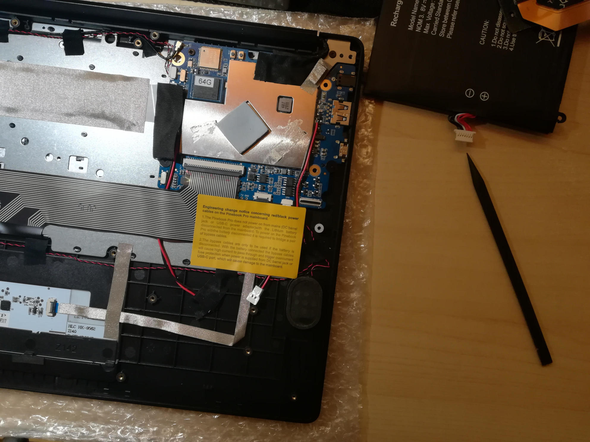
Once the battery screws are removed, it should be unplugged from the mainboard and removed. Note that there are two unconnected cables lying around, that should remain unconnected. They are used when the battery is disconnected entirely.
Step 4: Unplug the ribbon cables.
NOTE: you should remove the M.2 adapter board now if you have one installed. See elsewhere in this wiki for instructions on how to install/remove that piece.
There are several ribbon cables. To remove, flip up the tab and gentle pull the ribbon out.
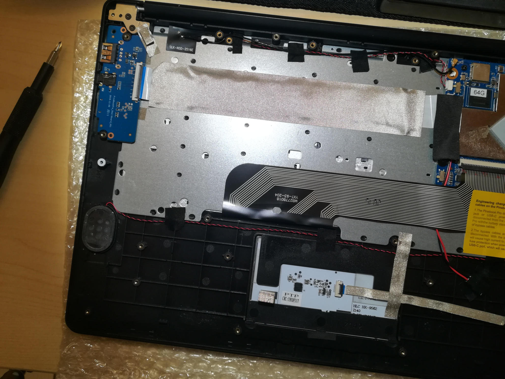
- One cable runs from the mainboard to the daughterboard underneath the battery. Detach from both ends. With the battery removed, detach from keyboard shell, and set aside for the new keyboard shell.
- One cable runs between the touchpad and the mainboard. Detach from both ends, and also set aside.
- One cable runs between the keyboard and the mainboard. This one remains attached to the keyboard and only needs to be detached from the mainboard.
- One cable from the LCD attaches near the lid hinge. It should be just unplugged.
Step 5: Detach microphone, speakers, and antenna.
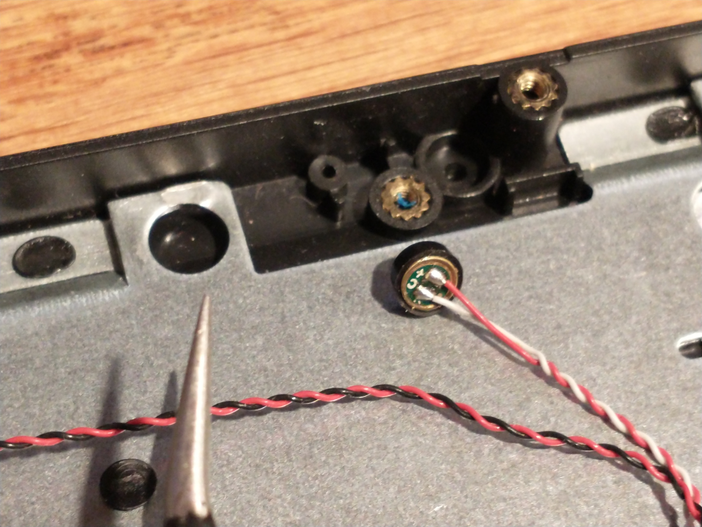
The speakers, microphone, and antenna don't have to be detached from the mainboard, but they need to be detached from the keyboard shell. The microphones are held in place by tape, and the speakers have sticky sides. The speakers are found obviously, but the microphones (two of) can be found between the battery and the hinge area. Each microphone can be carefully pulled/wedged out of its position by a small screwdriver or pick. The antenna, similar to the microphones, is found near the hinge area and to the top left of the battery.
Step 6: Remove mainboard and daughterboard.
At this point, the mainboard and daughterboards should be removed. When unscrewed (see Step 2) they should pull out fairly easily. Put them aside (including microphones and speakers if left attached.)
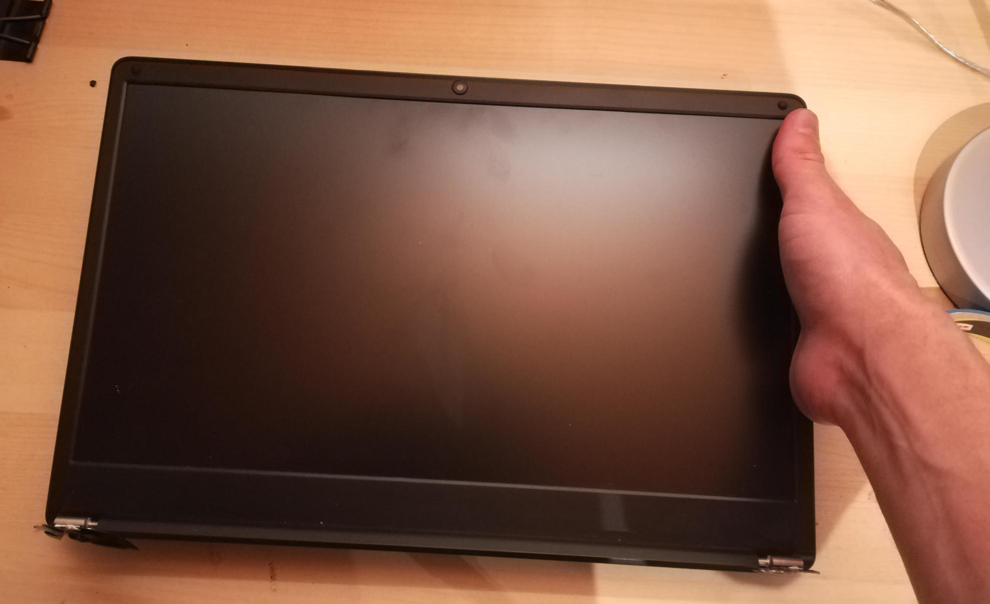
Step 7: Detach the LCD panel.
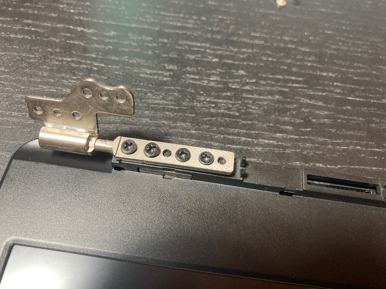
Step 2 didn't tell you, there are 6 more screws to remove here, 3 for each of the hinges. I recommend a PH1 bit for these screws. Unscrew these and the LCD panel will be able to be removed. You may have to jiggle or move the hinges for this. When detached, be sure to place the LCD panel such that the display is protected.
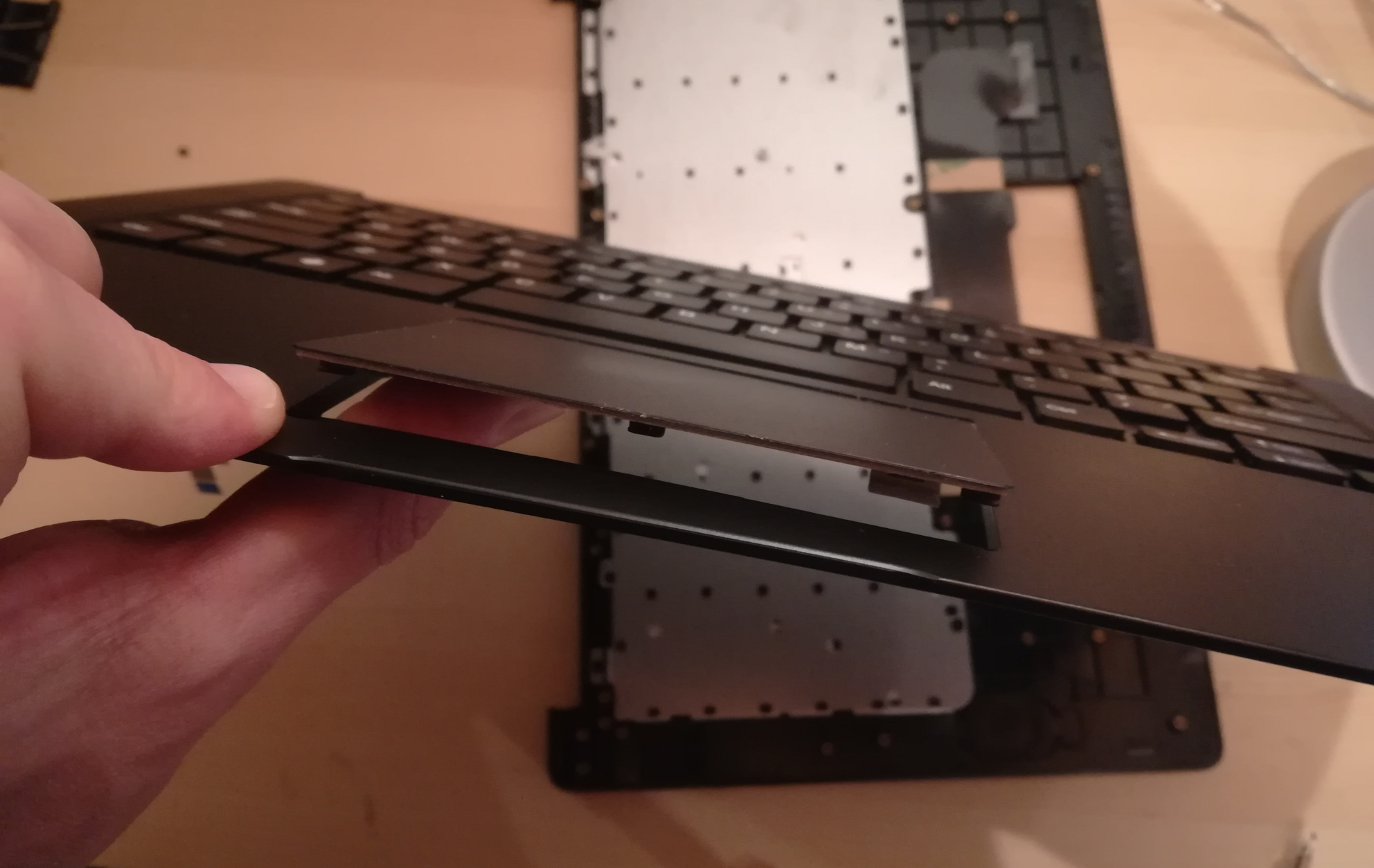
Step 8: Try not to break your touchpad
NOTE This section really feels like you're going to break something.
The touchpad is glued to the keyboard shell and it's glued well. There are two places it is glued to. If you can, only the middle must be force-detached. You will think you're going to break it. Gently apply increasing force until the glue begins to detach (you will hear a crackle as it comes off), and continue very slowly until the whole thing is detached. This may take minutes due to that feeling you're going to break it.
I found it helpful to lift the top left plastic bit on the keyboard to unstick that portion of the touchpad, then push on the top left portion of the touchpad to unstick the rest of the touchpad.
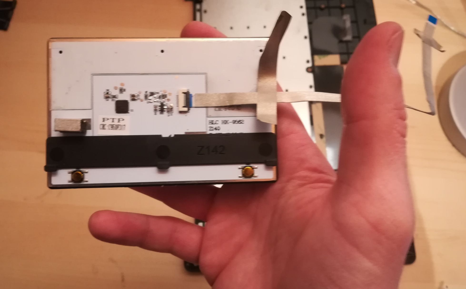
Step 9: Over the hill, touchpad goes into new shell.
In the new keyboard shell put the touchpad back where it was, hopefully the glue will remain sufficiently attached. If there is a glue issue, this guide unfortunately has no advice currently.
Step 10: Reattach the LCD panel.
The LCD panel should slot back into the keyboard frame, the same way it came out. If the hinges were moved, they should be *very* *gently* closed such that the LCD panel and keyboard closed like normal for the remaining steps.
Step 11: Tape it out.
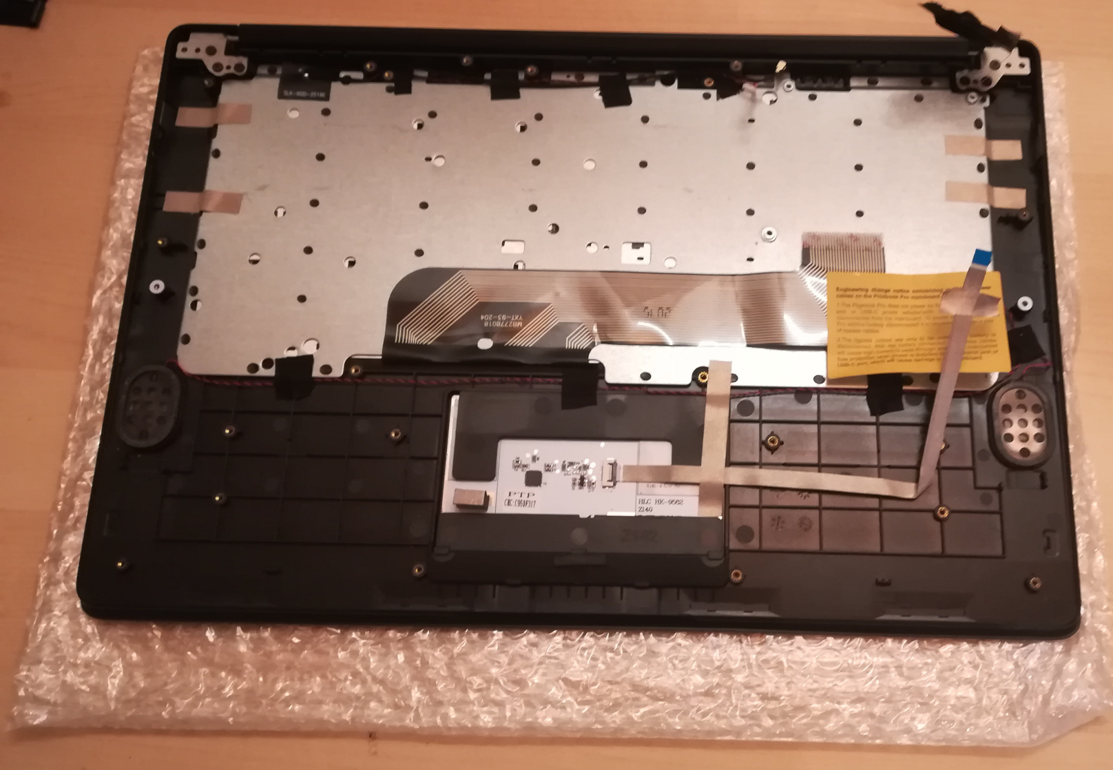
Move any tape from the old keyboard shell to the new one. These items protect the mainboard and daughterboard, and keep various wires in their right place. Some are grey and some are black. For tape that holds the speakers, microhones, or their cables in place, do not reattach yet.
Step 12: Board install.
Install the mainboard, the daughtboard, and their connecting ribbon cable. Be sure to put the boards in place, 2 large flat screws for the daughterboard, 3 large flat screws and one small screw for the mainboard, before attempting to place the ribbon.
Step 13: Microphone, speaker, and antenna install.
Reattach the microphones, antenna, and speakers to their respective areas, making sure that both are properly oriented - the speaker "out" faces up, and the microphone cables as connected must face up (these are opposite directions.)
Step 14: Reattach other ribbon cables.
NOTE: this would be a good time to attach/install the M.2 adapter board if that is desired. See elsewhere in this wiki for those instructions.
The LCD panel, keyboard and touchpad ribbon cables should be reattached. Make sure the flap is open, insert the ribbon into the slot (a portion of the cable will disappear), and push the flap down. The cable should not be easy to pull out.
Step 15: Reattach the battery, and final re-tape.
The battery should be installed with the 4 screws holding it in place, and the connector attached to the mainboard. Be sure to keep the two other cables remain unconnected. Ensure all wires and other tapes are held in place.
Step 16: Reattach the back panel.
Put the back panel back on, and reattach the 10 screws.
Step 17: If you changed from ISO to ANSI or from ANSI to ISO, you'll need to update your firmware now. See the links in Step 0 above.
Touchpad (trackpad)
Documentation for the touchpad can be found in Datasheets for Components and Peripherals. It is the only component of the Pinebook Pro held in place with strong adhesive tape. Here are some of its features:
- 2 actuating buttons.
- multi-touch functionality.
- A matte finish that your finger can slide along easily.
- A reasonable size (96mm × 64mm; diagonal: 115.378mm or 4.542”).
Troubleshooting
If you are having trouble using 2 fingers to scroll or emulate the click of a mouse's right-button, then try these solutions:
- Update the firmware.
- Keep your 2 fingers spread apart rather than close together.
- Individual programs might need to be configured specially.
- For smooth scrolling and gestures under X-Windows, Firefox should be launched with with the following environment variable assignment:
MOZ_USE_XINPUT2=1
- Experiment with other settings, via X-Windows Configuration or some other system preferences. For example, you could disable double-finger scrolling, and instead enable scrolling by sliding one finger along the edge of the touchpad.
Firmware
The touchpad controller is connected to the keyboard controller. All touchpad events go through the keyboard controller and its software, then to the keyboard controller's USB port. Note that the touchpad does have separate firmware (which has to be written through the keyboard controller). The touchpad vendor's firmware binary can be flashed from userspace using the following open source command-line utility:
- Kamil Trzciński's pinebook-pro-keyboard-updater.
Naturally, forks have begun to appear:
- Jack Humbert's fork
- Dragan Simic's fork. This one has recently delivered a much improved firmware from the vendor one, which greatly improves the control of the cursor (see this thread for discussion). Before installing this update, consider resetting to the defaults any configuration of your touchpad.
All Pinebook Pros shipped from the factory have the old buggy version installed so consider updating the keyboard and touchpad firmware with the latest fixes from Dragan.
Before updating any firmware, your Pinebook Pro should be either fully charged or, preferably, running from mains. This utility will be writing data to chips on the keyboard and touchpad, so a loss of power during any stage of the update can result in irrecoverable damage to your touchpad or keyboard.
The scripts ought to work on all operating systems available for the Pinebook Pro. Some operating systems may however, require installation of relevant dependencies. The instructions below assume a Debian desktop. To install these dependencies, newer Pinebook Pro models that come with Manjaro will require a different command.
There are two keyboard versions of the Pinebook Pro: ISO (vertical Enter key) and ANSI (horizontal Enter key). You need to know which model you have prior to running the updater. Firmware update steps for both models are listed below.
What you will need:
- Connection to internet for getting dependencies, either through WiFi or wired ethernet (USB dongle).
- Your Pinebook Pro fully charged or running from mains power.
- An external USB keyboard and mouse (or access to the Pinebook Pro via SSH. Please note that for some configurations, the SSH service might not be available without first having logged in once. In this case, you will definitely want at least an external keyboard or UART serial console).
ISO Model
From the terminal command line:
(Debian distros)
git clone https://github.com/dragan-simic/pinebook-pro-keyboard-updater
cd pinebook-pro-keyboard-updater
sudo apt-get install build-essential libusb-1.0-0-dev xxd
make
(Arch distros: eg Manjaro -- NOTE:build-essential, xxd are named differently. Arch linux does not split its packages as foo and foo-dev)
git clone https://github.com/dragan-simic/pinebook-pro-keyboard-updater
cd pinebook-pro-keyboard-updater
sudo pacman -Syu base-devel xxd-standalone libusb
make
The next steps are identical for both Debian and Arch distros.
Step 1
cd pinebook-pro-keyboard-updater
sudo ./updater step-1
sudo poweroff # do not use 'reboot'
Step 2 (after booting)
cd pinebook-pro-keyboard-updater
sudo ./updater step-2 iso
sudo poweroff # do not use 'reboot'
ANSI Model
From the terminal command line:
(Debian distros)
git clone https://github.com/dragan-simic/pinebook-pro-keyboard-updater
cd pinebook-pro-keyboard-updater
sudo apt-get install build-essential libusb-1.0-0-dev xxd
make
(Arch distros: eg Manjaro -- NOTE:build-essential, xxd are named differently. Arch linux does not split its packages as foo and foo-dev)
git clone https://github.com/dragan-simic/pinebook-pro-keyboard-updater
cd pinebook-pro-keyboard-updater
sudo pacman -Syu base-devel xxd-standalone libusb
make
The next steps are identical for both Debian and Arch distros.
Step 1
cd pinebook-pro-keyboard-updater
sudo ./updater step-1
sudo poweroff # do not use 'reboot'
Step 2 (after booting)
cd pinebook-pro-keyboard-updater
sudo ./updater step-2 ansi
sudo poweroff # do not use 'reboot'
When done, if some of the keys produce incorrect characters, please check your OS’s language settings. For ANSI users, the default OS may have shipped with English UK as the default language. You can change it to English US if desired.
Revised Firmware
In addition, you might consider using revised firmware data. This is one final step that should not require a reboot:
Step 3: ISO (after booting)
sudo ./updater flash-kb firmware/default_iso.hex
Step 3: ANSI (after booting)
sudo ./updater flash-kb firmware/default_ansi.hex
X Window System Configuration
When using X.Org display server the touchpad can be handled either by libinput or synaptic input drivers. The former allows to have shared configuration for both X.Org and Wayland but the latter provides more tunables (e.g. configurable edge scrolling, circular scrolling, mapping of multi-touch events to mouse buttons etc.)
Some forum members have found that an adjustment to X11 will allow finer motion in the touchpad. If you use the synaptic mouse/touchpad driver, use this command to make the change live:
synclient MinSpeed=0.2
You may experiment with different settings, but 0.25 was tested as helping noticeably.
To make the change persist across reboots, change the file /etc/X11/xorg.conf similar to below:
Section "InputClass"
       Identifier "touchpad catchall"
       Driver "synaptics"
       MatchIsTouchpad "on"
       MatchDevicePath "/dev/input/event*"
       Option "MinSpeed" "0.25"
EndSection
The line "Option "MinSpeed" "0.25"" is changed here.
Another forum user built on the above settings a little, and have found these to be very good:
synclient MinSpeed=0.25
synclient TapButton1=1
synclient TapButton2=3
synclient TapButton3=2
synclient FingerLow=30
synclient PalmDetect=1
synclient VertScrollDelta=64
synclient HorizScrollDelta=64
FingerLow has the same value as 'FingerHigh' in one config (30). It is believed to help reduce mouse movement as you lift your finger, but it's unknown whether synaptic works like this. You may find this config to be comfortable for daily use.
TabButton allows to just tab the touchpad instead of physically pressing it down (to get this click noise).
The right mouse click is emulated by tapping with two fingers on the touchpad. If you feel that this is not very responsive you can try this value:
synclient MaxTapTime=250
Some users may encounter an issue with the mouse jumping when typing when using libinput driver due to their hand hitting the touchpad which can be fixed by updating the X.Org settings to disable it while typing. One can disable the touchpad while typing by setting the below option in the X.Org config simliar to the previous example.
Option "DisableWhileTyping" "on"
The setting can be verified by using the xinput command to first list the devices and then listing the properties for the touchpad device. Exact commands to check this have been omitted for save of brevity. If DisableWhileTyping is shown enabled but does not appear to be working the issue may be due to the fact that the keyboard is connected to a USB bus which causes it to be seen as a external keyboard. Make sure you have libinput version 1.19.0 or later installed as it includes the necessary quirk.
Synaptic driver users can add syndaemon to their X11 session for the same effect.
Power Supply
- Input Power: 5 V DC, 15 W (current limit 3 A, see also inside photos of the factory-provided DC adapter: top, bottom)
- Mechanical: 3.5 mm OD / 1.35 mm ID, barrel jack (also known as DC 35135 socket)
- USB-C 5 V, 12.5 W (current limit is at 2.5 A regardless of the USB PD negotiations result)
- Only use one power input at a time, barrel jack or USB-C (note: some powerful Type-C adapters have rather limited current for 5 V operation, and e.g. 2 A won't be enough to run the system and charge the battery at the same time, so check the specs)
Pinebook Pro power and charging explains how exactly external power supply is used to run the system and charge the battery, as there are several counter-intuitive details about the process.
LEDs
In total, there are four LEDs on the Pinebook Pro, three of which are placed in the top-left side of the keyboard, and one near the barrel port:
- The red LED next to the barrel port indicates charging, in three ways. First, it will illuminate steadily when either the barrel jack power supply or a USB Type-C charger is connected to the Pinebook Pro, and the charging is active (that means power is supplied to the battery and system in parallel, and if it's not enough the battery can still be discharging). Second, if the battery is at 100 %, the LED will remain turned off regardless of the connected power input (however, this is not possible for more than a split-second when the system is running). Third, this LED will flash at 0.5 Hz if there are any problems that prevent charging, such as the battery becoming too hot. To fully understand all the nuances, read the corresponding article.
- The power indicator LED, above the keyboard, supports three different colors: green, amber and red. It is also capable of flashing to indicate eMMC activity, with proper software support. In the default Debian with MATE build, green LED means power and red means suspend (amber is unused).
- The green NumLock LED, above the keyboard.
- The green CapsLock LED, above the keyboard.
The NumLock and CapsLock LEDs serve their usual purposes on a keyboard, but they also have a secondary function. When the privacy switches get activated they blink to confirm that the switch has been activated.
Webcam
- Streaming video resolutions supported, (uncompressed):
- 320 x 240
- 640 x 480
- 800 x 600
- 1280 x 720
- 1600 x 1200
- Still frame resolutions supported:
- 160 x 120
- 176 x 144
- 320 x 240
- 352 x 288
- 640 x 480
- 800 x 600
- 1280 x 720
- 1600 x 1200
Audio
ALSA configuration
If you do not have the integrated sound card selected as the default, create /etc/asound.conf with the following contents:
defaults.pcm.!card rockchipes8316c
defaults.ctl.!card rockchipes8316c
If you want to enable software mixing (dmix) by default for all ALSA apps (works without Pipewire or PulseAudio), make /usr/share/alsa/cards/simple-card.conf file contain this:
# default with dmix/dsnoop
simple-card.pcm.default {
	@args [ CARD ]
	@args.CARD {
		type string
	}
	type asym
	playback.pcm {
		type plug
		slave.pcm {
			@func concat
			strings [ "dmix:CARD=" $CARD ",RATE=44100" ]
		}
	}
	capture.pcm {
		type plug
		slave.pcm {
			@func concat
			strings [ "dsnoop:CARD=" $CARD ",RATE=44100" ]
		}
	}
}
Pop/click suppression workaround
If you're annoyed by loud popping and clicking sounds, which occur a few seconds after the sound playback stops as a result of the components of the audio chain being turned on and off automatically by the Linux kernel, you can execute the following command manually, or automatically on boot using the tmpfiles.d systemd feature, for example:
echo 50 > /sys/kernel/debug/asoc/rockchip,es8316-codec/dapm_pop_time
This is a workaround because it effectively (ab)uses a built-in debugging feature of the Linux kernel's audio subsystem, and one of the downsides is that a lot of messages are produced in the kernel log whenever the components of the audio chain are turned on and off automatically by the kernel.
Speaker polarity workaround
On newer Pinebook Pro batches, the inverted built-in speaker polarity issue has been fixed. On these units, the speaker polarity can be made reversed again by the alsa-ucm-conf package, which configures ALSA devices continuously. One workaround would be to remove the package, and the speaker polarity will no longer be set incorrectly. However, this also prevents the built-in speakers from being muted when an output device is plugged into the aux port.
Another workaround is to edit file /usr/share/alsa/ucm2/Rockchip/es8316/HiFi.conf and change all instances of R Invert to Normal. This is a workaround because it's likely to be overwritten and lost if the alsa-ucm-conf package is updated.
Microphones
While it has been said that some Pinebook Pro units contain only one microphone despite having two labeled microphone holes on the outer casing, other units do indeed contain two microphones. It is presently unclear which batches have either configuration. Units from the initial community batch of 1000 units (following the initial 100) are believed to contain two, populating both labeled holes.
The wires leading to both microphones connect to the mainboard with a small white plastic connector, located directly adjacent to the ribbon cable attachment point for the keyboard interface.
Built-in microphones not working
If pavucontrol input doesn't show microphone activity try changing the privacy switches. If the switches are in the correct place and microphone input isn't working you can run alsamixer from the command line, hit F6 and select the es8316, hit F4 to get to the capture screen, select the bar labeled ADC, increase the gain to 0 dB, change the audio profile in pavucontrol to another one with input. Additionally you may want to modify ADC PGA to get the levels to where you want them. If that still hasn't fixed it you may want to check that the microphone connector is plugged in (see the section Technical Reference).
External wired microphone not working
If you connect a headset with a microphone, you might need to open alsamixer, change card to es8316, and change option Differential Mux from lin1-rin1 to lin2-rin2.
Bluetooth and WiFi
Hardware Overview
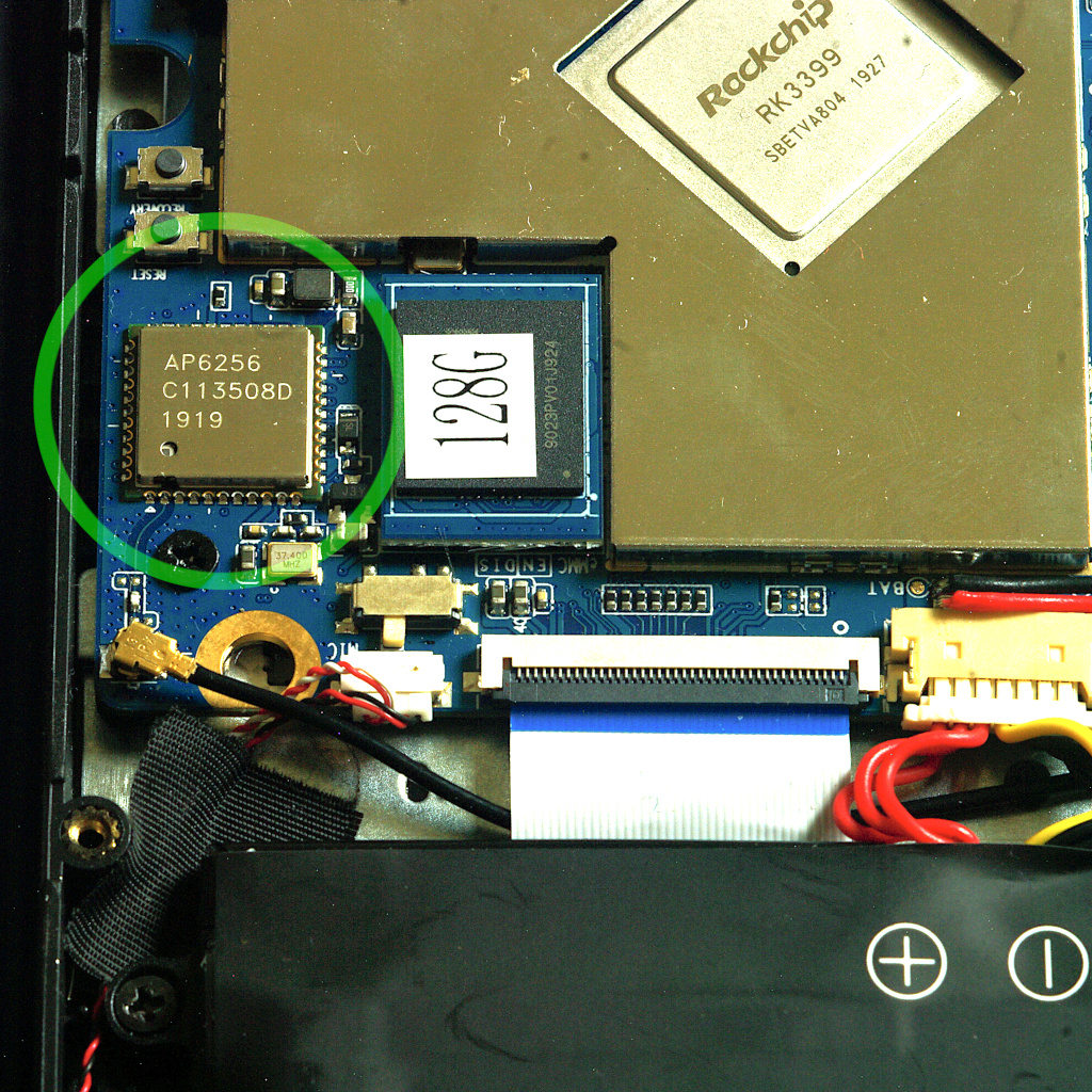
The Pinebook Pro contains an AMPAK AP6256 wireless module to provide Wi-Fi (compliant to IEEE 802.11ac) and Bluetooth (compliant to Bluetooth SIG revision 5.0). The module contains a Broadcom transceiver IC, believed to be the BCM43456, as well as the support electronics needed to allow the Wi-Fi and Bluetooth modes to share a single antenna.
The wireless module interfaces with the Pinebook Pro’s system-on-chip using a combination of three interfaces: Bluetooth functionality is operated by serial UART and PCM, while the Wi-Fi component uses SDIO. It is unknown if the module’s Bluetooth capabilities are usable under operating systems that do not support SDIO.
The module’s RF antenna pin is exposed on the mainboard via a standard Hirose U.FL connector, where a coaxial feedline links it to a flexible adhesive antenna situated near the upper right corner of the Pinebook Pro’s battery. As the RF connector is fragile and easily damaged, it should be handled carefully during connection and disconnection, and should not be reconnected frequently.
Issues
Problems have been reported with the Wi-Fi transceiver’s reliability during extended periods of high throughput, especially on the 2.4 GHz band. While the cause of this has yet to be determined, switching to the 5 GHz band may improve stability.
Since the Bluetooth transceiver shares both its spectrum and antenna with 2.4 GHz Wi-Fi, simultaneous use of these modes may cause interference, especially when listening to audio over Bluetooth. If Bluetooth audio cuts out frequently, switching to the 5 GHz band – or deactivating Wi-Fi – may help.
Wi-Fi Capabilities
Wi-Fi on the Pinebook Pro is capable of reaching a maximum data transfer rate of approximately 433 megabits per second, using one spatial stream. The transceiver does not support multiple spatial streams or 160-MHz channel bandwidths.
The Wi-Fi transceiver supports the lower thirteen standard channels on the 2.4 GHz band, using a bandwidth of 20 MHz. At least twenty-four channels are supported on the 5 GHz band, spanning frequencies from 5180 to 5320 MHz, 5500 to 5720 MHz, and 5745 to 5825 MHz, with bandwidths of 20, 40, or 80 MHz. This might vary depending on the country you specify in the wireless settings, see iw reg get; iw list.
Maximum reception sensitivity for both bands is approximately -92 dBm. The receiver can tolerate input intensities of no more than -20 dBm on the 2.4 GHz band, and no more than -30 dBm on the 5 GHz band. Maximum transmission power is approximately +15 dBm for either band, falling further to approximately +10 dBm at higher data transfer rates on the 5 GHz band.
With current available drivers and firmware, the Wi-Fi interface supports infrastructure, ad-hoc, and access-point modes with satisfactory reliability. Monitor mode is not presently supported. Wi-Fi Direct features may be available, but it is unclear how to make use of them under Linux.
Be aware that Linux userspace utilities, such as iw, may report inaccurate information about the capabilities of wireless devices. Parameter values derived from vendor datasheets, or direct testing, should be preferred to the outputs of hardware-querying tools. That said, if a certain feature is not reported by iw it means the currently running kernel driver plus firmware combination doesn't support it, even when the hardware is capable.
WPA3 PSK support should be possible with iwd but not wpa_supplicant, see this ticket for details.
Bluetooth Capabilities
Bluetooth data transfer speeds have an indicated maximum of 3 megabits per second, but it is unclear what practical data rates can be expected. Audio streaming over Bluetooth is functioning normally, as is networking. Bluetooth Low-Energy functions, such as interacting with Bluetooth beacons, have not yet been tested conclusively.
The Bluetooth transceiver supports all 79 channel allocations, spanning frequencies from 2402 MHz to 2480 MHz. Reception sensitivity is approximately -85 dBm, with a maximum tolerable reception intensity of -20 dBm. Bluetooth transmission power is limited to +10 dBm.
Disabling Bluetooth
To disable Bluetooth under Linux once:
sudo rfkill block bluetooth
To confirm if Bluetooth under Linux is disabled:
rfkill
To disable Bluetooth on boot (note: for distributions such as Manjaro XFCE see the step below):
sudo systemctl enable rfkill-block@bluetooth
To disable Bluetooth on certain distributions, such as Manjaro XFCE, right click on the Bluetooth panel icon, select plugins, then PowerManager, then configuration and then deselect the auto power on option
LCD Panel
- Model: BOE NV140FHM-N49
- 14.0" (35.56 cm) diagonal size
- 1920x1080 resolution
- 60 Hz refresh rate
- IPS technology
- 1000:1 contrast
- 250 nit brightness
- 63% sRGB coverage
- 6-bit color
- 30-pin eDP connection
External ports list
Here are a list of the external ports. See Technical Reference - Expansion Ports for port specifications.
- Left side
- Barrel jack for power, (with LED)
- USB 3, Type A
- USB 3, Type C
- Right side
- USB 2, Type A
- Standard headset jack
- MicroSD card slot
Using the serial console UART
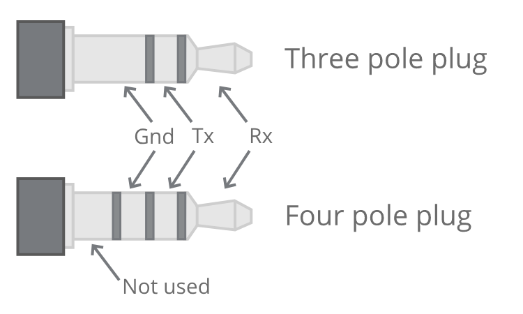
Serial console UART is enabled by flipping the UART switch to the ON position (item 9). To do so, you need to remove the Pinebook Pro's bottom cover by following the disassembly and reassembly guidelines. The OFF position is towards the touchpad, while the ON position is towards the display hinges.
With the UART switch in the ON position, the console is relayed via the headset jack, on which the audio output is no longer available. Please ensure that you are using a 3.3 V UART interface (such as the CH340, FTDI-232R, or PL2303, which are available in both 3.3 V and 5 V variants) to avoid damage to the RK3399 SoC. Older version of the serial console cable sold by the Pine Store used wrong voltage level and should not be used, see this forum thread for further information. Recent version of the same cable uses the right voltage level, which can also be checked by measuring the voltage on the TX ring.
Insert the USB plug of the cable into a USB port on the machine that you will use to monitor the Pinebook Pro's serial console, ensuring that the audio jack of the serial cable is be fully inserted into the Pinebook Pro's headphone port. Run lsusb in a terminal and you should see a line similar to this:
Bus 001 Device 058: ID 1a86:7523 QinHeng Electronics HL-340 USB-Serial adapter
Serial console output should now be accessible on the respective machine using a terminal emulator, such as screen, picocom or minicom. Here are a few examples of how to invoke a terminal emuator:
screen /dev/ttyUSB0 1500000picocom /dev/ttyUSB0 -b 1500000minicom -D /dev/ttyUSB0 -b 1500000
Using the optional NVMe adapter
The optional NVMe adapter allows the use of M.2 SSDs that support the NVMe standard (SATA is not supported). The adapter supports M and M+B keyed devices, in both 2242 and 2280 physical sizes, which are the most commonly available. In addition, 2230 and 2260 sizes are also supported, though NVMe devices that use those sizes are rare.
Make sure to read the notes in Pinebook Pro Hardware Accessory Compatibility#NVMe SSD drives before selecting an M.2 SSD for your Pinebook Pro, because there are certain limitations. Once you have fitted and tested your NVMe drive, please consider adding a note to that page
Please see a separate section that describes reported issues with the NVMe drives in Pinebook Pro.
Installing the adapter
The V2.1-2019-0809 SSD adapter that shipped with the initial Pinebook Pro batches had significant issues. A repair kit will be shipped to address those issues. (If necessary, it can be modified to work. There is an unofficial tutorial on the forums describing these modifications.)
The updated SSD adapter, labeled V2-2019-1107, takes into account the prior problems with touchpad interference. New orders as of Feb. 22nd, 2020 will be the updated adapter.
This is the link to the Pinebook Pro accessories in the store: https://pine64.com/?v=0446c16e2e66
Actual installation instructions are a work in progress. Unofficial instructions for installing V2-2019-1107 can be found here.
Post NVMe install power limiting
Some NVMe SSDs allow reducing the maximum amount of power. Doing so may reduce the speed, but it may be needed in the Pinebook Pro to both improve reliability on battery: Some NVME may be stable with default settings when runnning on AC power but cause frequent kernel panics (system freeze with power LED blinking red/green) when running on battery. Reducing NVME power drain solves this in some cases. And reducing power used gives better battery life. Here are the commands to obtain and change the power settings. The package 'nvme-cli' is required to run these commands. The example shows how to find the available power states, and then sets it to the lowest, non-standby setting, (which is 3.8 watts for the device shown):
$ sudo nvme id-ctrl /dev/nvme0
NVME Identify Controller:
...
ps    0 : mp:9.00W operational enlat:0 exlat:0 rrt:0 rrl:0
         rwt:0 rwl:0 idle_power:- active_power:-
ps    1 : mp:4.60W operational enlat:0 exlat:0 rrt:1 rrl:1
         rwt:1 rwl:1 idle_power:- active_power:-
ps    2 : mp:3.80W operational enlat:0 exlat:0 rrt:2 rrl:2
         rwt:2 rwl:2 idle_power:- active_power:-
ps    3 : mp:0.0450W non-operational enlat:2000 exlat:2000 rrt:3 rrl:3
         rwt:3 rwl:3 idle_power:- active_power:-
ps    4 : mp:0.0040W non-operational enlat:6000 exlat:8000 rrt:4 rrl:4
         rwt:4 rwl:4 idle_power:- active_power:-

$ sudo nvme get-feature /dev/nvme0 -f 2
get-feature:0x2 (Power Management), Current value:00000000
$ sudo nvme set-feature /dev/nvme0 -f 2 -v 2 -s
set-feature:02 (Power Management), value:0x000002
Some NVMe SSDs don't appear to allow saving the setting with "-s" option. In those cases, leave off the "-s" and use a startup script to set the non-default power state at boot. If you want to test performance without saving the new power setting semi-permanantly, then leave off the "-s" option.
On systemd based distributions like Manjaro, a non-default power state for an NVME can be set using a systemd service. This is useful in cases where the NVME drive does not save the power state and/or uses APST. An example systemd service, nvme-throttle.service, is shown below:
[Unit]
Description=Throttles NVME to lesss power hungry mode
After=suspend.target hibernate.target hybrid-sleep.target suspend-then-hibernate.target

[Service]
Type=oneshot
ExecStart=/usr/bin/nvme set-feature /dev/nvme0 -f 2 -v 1

[Install]
WantedBy=multi-user.target suspend.target hibernate.target hybrid-sleep.target suspend-then-hibernate.target
Here the value after "-v" is the maximum power state that you want your SSD to use. This will be executed at system startup, and every time your system exits any suspend mode that might reset the SSD to default values.
This file needs to be placed in the /etc/systemd/system directory. Afterwards, to activate the service, run:
systemctl daemon-reload
systemctl enable --now nvme-throttle.service
There is another power saving feature for NVMes, APST, (Autonomous Power State Transitions). This performs the power saving & transitions based on usage. To check if you have a NVMe SSD with this feature:
$ sudo nvme get-feature -f 0x0c -H /dev/nvme0
Information for this feature, (on a Pinebook Pro), is a work in progress. It is enabled by default in latest Manjaro kernels and reported to work. On some NVME SSDS (WD), APST is compatible with limiting NVME maximum power: APST will work and not exceed maximum power state defined using previous method.
Using as data drive
As long as the kernel in use has both the PCIe and NVMe drivers, you should be able to use a NVMe drive as a data drive. It can automatically mount when booting from either the eMMC or an SD card. This applies to Linux, FreeBSD, and Chromium, using the normal partitioning and file system creation tools. Android requires testing.
Using as OS root drive
The SoC does not include the NVMe boot code, so the NVMe is not in the SoC's boot order. However, using the U-Boot update script from the mrfixit2001 Debian or Arglebargle's modified script, and the modified u-boot images provided by forum user pcm720, you can now add support to boot from an NVMe drive. Binary images are useable with SD, eMMC, and SPI flash. For OS images using the mainline kernel, there are a few variants of U-Boot available that also support NVMe as the OS drive. Though these may require writing the U-Boot to the SPI flash for proper use of the NVMe as the OS drive.
The current boot order, per last testing, for this modified U-Boot is:
- MicroSD
- eMMC
- NVMe
For more information, please refer to the forum post.
It is also possible to initially boot off an eMMC or SD card, then transfer to a root file system on the NVMe. Currently, it is necessary to have the U-Boot code on an eMMC or SD card. (A forum member posted here about using a modified version of U-Boot with NVMe drivers, that uses /boot and / off the NVMe drive. So this may change in the future.)
Please see Bootable Storage.
Caring for the Pinebook Pro
Bypass Cables
The mainboard features two bypass cables that are to be used only with the battery disconnected. The two bypass cables are disconnected by default. The female (10) male (6) ends of the bypass cables can be connected to provide power to the mainboard if you need to run your Pinebook Pro with no battery. Please refer to this engineering notice for more details.
Connecting the bypass cables together effectively connects the charger input where the battery output is, which also bypasses the charging circuit inside the Pinebook Pro. Thus, with the bypass cables connected together, the charger powers the Pinebook Pro directly, just like the battery does it when the laptop is running on battery power. This also means that no input current limiting is any longer in place, making it possible to draw more than 3 A from the charger, and to trigger its overcurrent protection, which may cause operating system instability and crashes.
Despite the bypass cables having two conductors, they are used as a single conductor. Having both wires soldered together on either side of the bypass cables is normal, and such load-sharing design allows use of a compact connector on the bypass cables.
When removing the large RF shield found on the mainboard, for example when shorting the pins on the SPI chip, make absolutely sure to align it correctly while putting it back. Failing to do so can result in shorting the battery to the ground, due to the close proximity of the solder pads for the bypass cables, which would prevent the normal operation and effectively cause a fire hazard. It is highly recommended to disconnect the battery before removing the RF shield, and before putting it back.
Self-Service Step-by-Step Guides
These are self-service instruction guides for the disassembly of the 14-inch Pinebook, but they still almost directly apply to the Pinebook Pro:
Assembling it back requires the described steps to be performed in the reverse order.
Using the SPI flash device
See Pinebook Pro SPI for details.
The Pinebook Pro comes with a 128Mbit, (16MByte), flash device suitable for initial boot target, to store the bootloader. The SoC used on the Pinebook Pro boots from this SPI flash device first, before eMMC or SD card. At present, April 19, 2020, the Pinebook Pros ship without anything programmed in the SPI flash device. So the SoC moves on to the next potential boot device, the eMMC. ARM/ARM64 computers do not have a standardized BIOS, yet.
Here is some information on using the SPI flash device:
- You need the kernel built with SPI flash device support, which will supply a device similar to: /dev/mtd0
- The Linux package below, will need to be available: mtd-utils
- You can then use this program from the package to write the SPI device:
flashcp <filename> /dev/mtd0
Even if you need to recover from a defective bootloader written to the SPI flash, you can simply short pin 6 of the SPI flash to GND and boot. This will render the SoC bootrom unable to read from the SPI flash and have it fall back to reading the bootloader from other boot media like the eMMC or Micro SD card.
The procedures described above are a lot less risky than attaching an external SPI flasher and do not require any additional hardware. At present, April 19th, 2020, there is no good bootloader image to flash into the SPI flash device. This is expected to change, as there are people working on issue.
Software tuning guide
The software tuning guides can be found in the article Pinebook Pro Software Tuning Guide.
Troubleshooting guide
Do not panic if something goes wrong or in an unexpected way. Instead, stop and consider carefully how to undo something, or how to redo it. This particularly applies when flashing a new operating system, or flashing new firmware to the keyboard or touchpad. If everything fails, consider reporting the issue on the forums, with as many relevant details as available.
Please, have a look at the Pinebook Pro Troubleshooting Guide, which details a number of issues you may encounter.
Hardware/Accessory Compatibility
Please contribute to the hardware/accessory compatibility page, which lists the status of hardware tested with the Pinebook Pro. Available hardware categories include the following:
Disassembly and Reassembly
There are a few mandatory precautions to be taken:
- Do not open the laptop by lifting the lid while the Pinebook Pro bottom cover is removed - this can cause structural damage to the hinges and/or other plastic components of the chassis such as the IO port cut-outs.
- When removing the back cover plate, *do not, under any circumstances, slide your fingertips between the metal shell and the plastic frame!* The back cover plate edges are sharp, and when combined with the pressure and movement generated from, specifically, attempting to slide the tips of your fingers along the bottom edge of the plate along the lid-hinge, they *will* slice open the tips of your fingers like a knife.
- When removing the back cover plate, use care to avoid damaging the speakers. They can be stuck to the back cover with double-sided tape, and the thin wires are very delicate. Newer Pinebook Pro laptops (as of the May 2021 batch, and perhaps earlier) seem to lack the double-sided tape to the rear cover, instead opting for tape or glue that makes them stick to the front cover. Nevertheless, be gentle when removing the back cover.
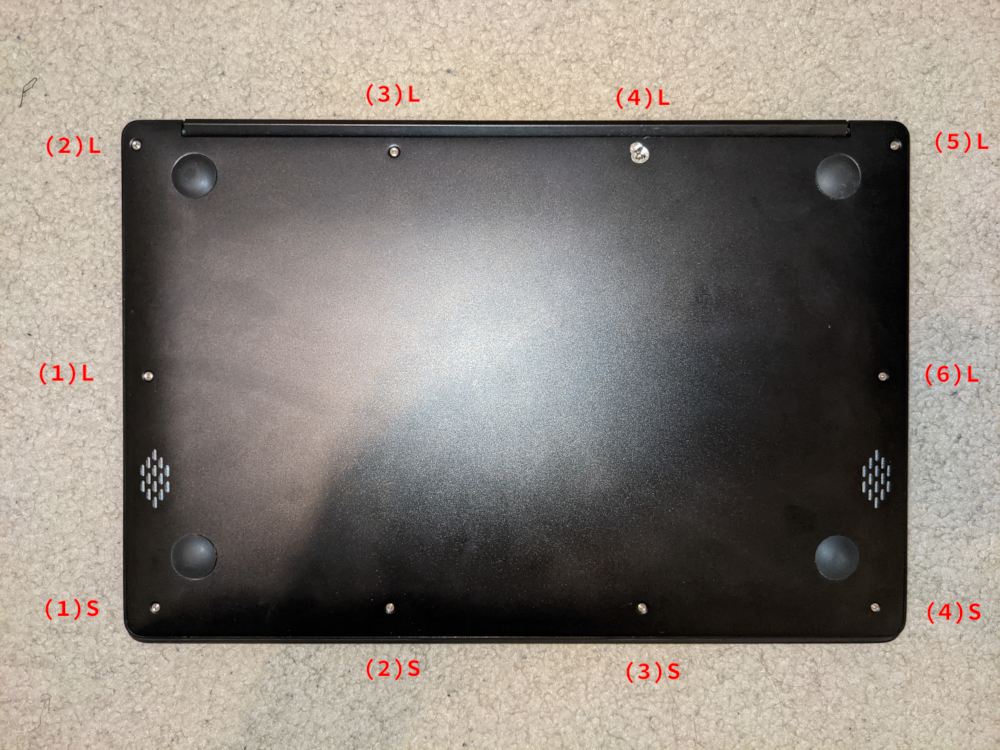
When disassembling the laptop make sure that it is powered off and folded closed. To remove the bottom cover of the Pinebook Pro, first remove the ten (10) Phillips head screws that hold the bottom section of the laptop in place. There are four (4) short screws along the front edge, and six (6) long screws along the 3 remaining sides. Remove the cover from the back where the hinges are situated by lifting it up and away from the rest of the chassis. The aluminum case is held on only by screws. There are no plastic snaps, and the shell should pull away without any effort. If you experience any resistance at all stop and ensure all ten (10) screws are accounted for.
During reassembly, make sure that the back-screw standoffs are in place and seated correctly. Before replacing the aluminum back-plate, ensure that the speakers are properly seated by pressing gently on the hard plastic edge of the speaker module. Slide the bottom section into place so it meets the front lip of the keyboard section. Secure the front section (where the touchpad is located) in place using the short screws in the front left and right corners. Then proceed to pop in the bottom panel into place. Secure the bottom section (where hinges are located) by screwing in the left and right corners. Then screw in the remaining screws and run your finger though the rim on the chassis to make sure its fitted correctly. Note that the front uses the remaining 4 short screws.
The screws are small and should only be finger tight. Too much force will strip the threads. If after installing screws the back cover plate has not seated properly on one side (which may be caused by the aforementioned misseating of the speakers), open the display and hold the base on either side of the keyboard and gently flex the base with both hands in opposing directions. Once the side pops further in, then recheck the screws on that side. If it does not pop back in, re-open the machine and check for misseated components.
A basic 3D model to print replacement standoffs for the back cover screws is available on Thingiverse, until the official drawings or 3D models are made available.
Many units come with the hinges too stiff from the factory. You can tell if it affects your device by carefully observing if operating the lid on a fully assembled notebook flexes the case. This repeated flexing can lead to plastic and metal fatigue and eventually broken parts. Consider carefully using a flat screwdriver or similar object to unbend the hinges a bit by wedging it into the slot (requires the display part to be fully detached from the main body).
Display Disassembly
It is not recommended to adjust the position of the lid when the bottom cover is removed, because the bottom cover provides structural strength, so the lid should be open fully as the first step, before starting any disassembly of the laptop. After opening the lid, remove the bottom cover by following the instruction found in the section above. Alternatively, you can keep the lid closed and remove the screws that hold the hinges to the main laptop body, as described in Pinebook Service Step by Step Guides.
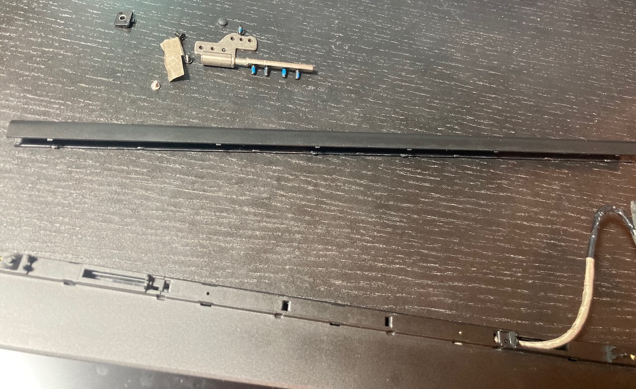
Parts of the hinge mechanism, as well as the screws that hold the hinges to the lid, are hidden behind an elongated plastic U-shaped cover that snaps in place using latches. Use a dedicated plastic prying tool or a guitar pick to gently pry the cover and remove it, starting from the outer edge. Once you pry the cover to a certain extent, it should be possible to remove it fully using only your hands. The U-shaped cover is rather sturdy, but still be careful not to break or bend it.
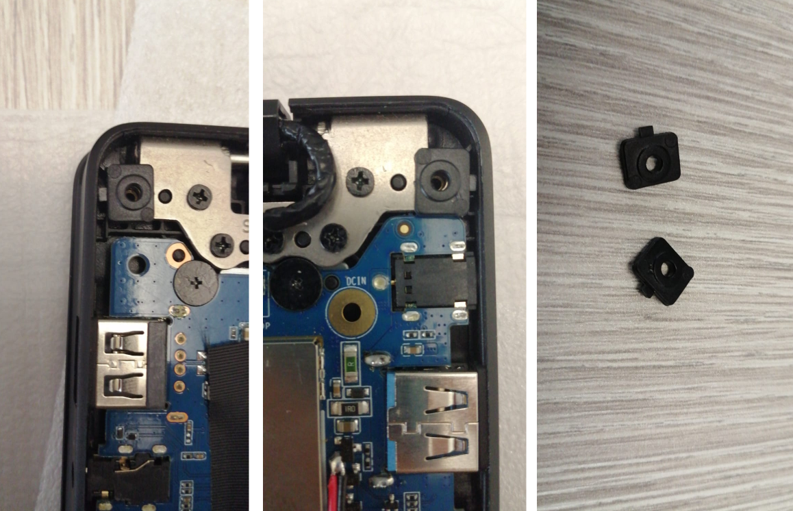
There are two small screws hidden underneath the two small rubber nubs on the upper part of the screen bezel, so first gently remove the nubs and then remove the screws. The screen bezel is held in place with a combination of latches and some adhesive tape, which is there to prevent dust ingress. The adhesive isn't very strong, and the bezel is capable of flexing back into shape after being twisted to a certain extent. There is more adhesive on the bottom part of the screen bezel, so be more careful while prying that section apart. Use the same prying tool that you used for the U-shaped cover, and work it around the outer edges of the screen bezel.
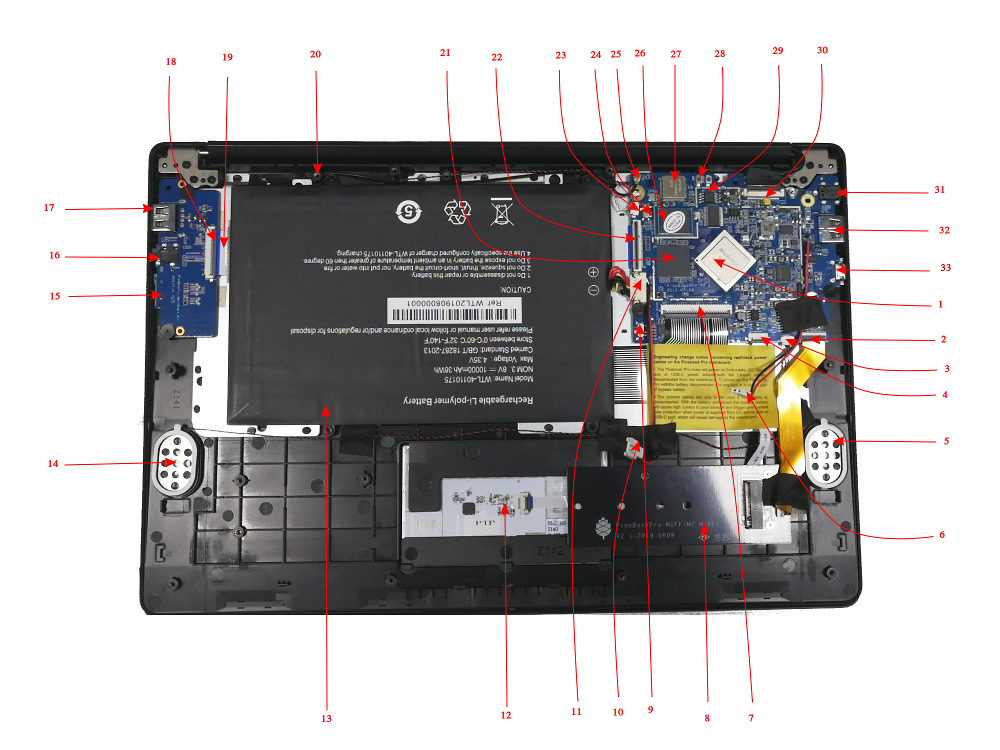
Internal Layout
Main chips
- RK3399 system-on-chip (1)
- LPDDR4 SDRAM (21)
- SPI NOR flash memory (29)
- eMMC flash memory module (26; Note: Some datasheets indicate a low supported number of mating cycles.)
- WiFi/BT module (27)
Mainboard Switches and Buttons
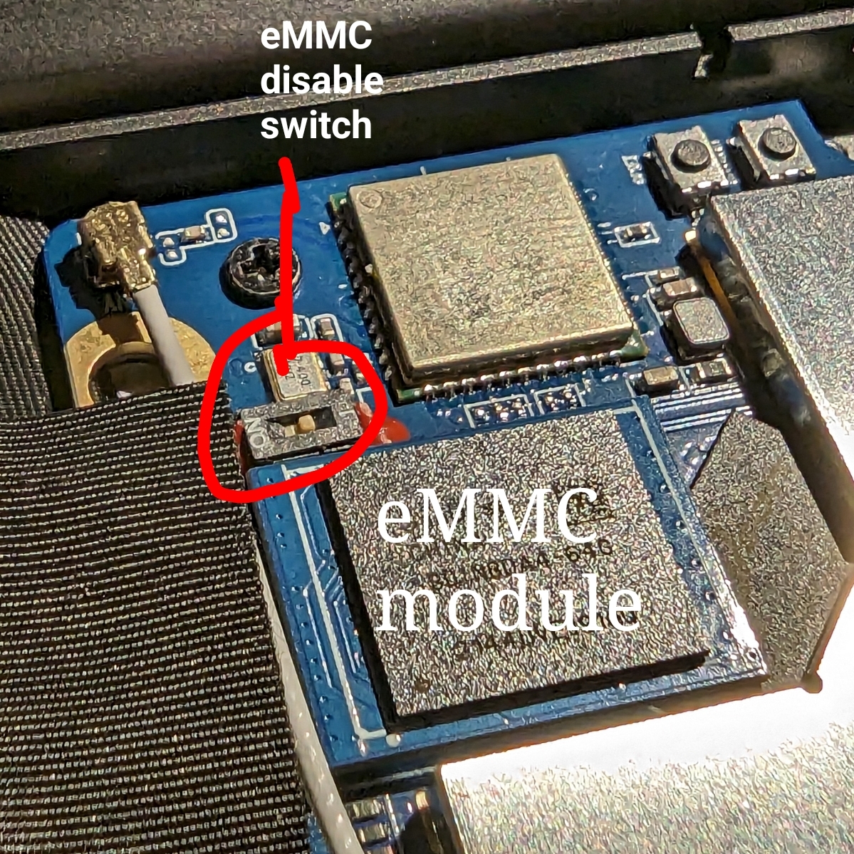
There are two switches on the main board: disabling the eMMC module (24), and enabling serial console UART (9) via headphone jack.
The Reset and Recovery buttons (28): the reset button performs an immediate reset of the laptop. The Recovery button is used to place the device in maskrom mode. This mode allows flashing eMMC using Rockchip tools (e.g. rkflashtools).
Key Internal Parts
| Number | Type | Descriptor |
|---|---|---|
| 1 | Component | RK3399 System-On-Chip |
| 2 | Socket | PCIe x4 slot for optional NVMe adapter |
| 3 | Socket | Speakers socket |
| 4 | Socket | Touchpad socket |
| 5 | Component | Left speaker |
| 6 | Connector | Power bridge connector |
| 7 | Socket | Keyboard Socket |
| 8 | Component | Optional NVMe SSD adapter |
| 9 | Switch | UART/Audio switch - enables serial console UART via headphone jack |
| 10 | Socket | Power bridge socket |
| 11 | Socket | Battery socket |
| 12 | Component | Touchpad |
| 13 | Component | Battery |
| 14 | Component | Right speaker |
| 15 | Socket | MicroSD card slot |
| 16 | Socket | Headphone / serial console UART jack |
| 17 | Socket | USB 2.0 Type A |
| 18 | Socket | Daughterboard-to-mainboard ribbon cable socket |
| 19 | Cable | Daughterboard-to-mainboard ribbon cable |
| 20 | Component | microphone |
| 21 | Component | LPDDR4 RAM |
| 22 | Socket | Mainboard-to-daughterboard ribbon cable socket |
| 23 | Socket | Microphone socket |
| 24 | Switch | Switch to hardware disable eMMC |
| 25 | Antenna | BT/WiFI antenna |
| 26 | Component | eMMC flash memory module |
| 27 | Component | BT/WiFi module chip |
| 28 | Buttons | Reset and recovery buttons |
| 29 | Component | SPI flash storage |
| 30 | Socket | eDP LCD socket |
| 31 | Socket | Power in barrel socket |
| 32 | Socket | USB 3.0 Type A |
| 33 | Socket | USB 3.0 Type C |
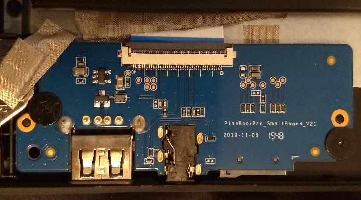
Smallboard detailed picture
Bootable Storage
Boot sequence details
The RK3399's mask 32KB ROM boot code looks for the next stage of code at byte off-set 32768, (sector 64 if using 512 byte sectors). This is where U-Boot code would reside on any media that is bootable, RK3399 boot sequence
Boot devices
The Pinebook Pro is capable of booting from eMMC, USB 2.0, USB 3.0, or an SD card. It cannot boot from USB-C. The boot order of the hard-coded ROM of its RK3399 SoC is: SPI NOR, eMMC, SD, USB OTG.
At this time, the Pinebook Pro ships with a Manjaro + KDE build with u-boot on the eMMC. Its boot order is: SD, USB, then eMMC.
(An update has been pushed for the older Debian + MATE build that improves compatibility with booting other operating systems from an SD card. In order to update, fully charge the battery, establish an internet connection, click the update icon in the toolbar, and then reboot your Pinebook Pro. Please see this log for details.)
Please note that PCIe, the interface used for NVMe SSD on the Pinebook Pro, is not bootable on the RK3399 and therefore is not a part of the boot hierarchy. It is possible to run the desired OS from NVMe by pointing extlinux on the eMMC to rootfs on the SSD. This requires uboot, the Kernel image, DTB, and extlinux.conf in a /boot partition on the eMMC.
eMMC information
The eMMC appears to be hot-pluggable. This can be useful if trying to recover data or a broken install. Best practice is probably to turn the eMMC switch to off position before changing modules. Note that the enable/disable label on the silkscreen is incorrect on some board revisions (known bad on v2.1).
The eMMC storage will show up as multiple block devices:
- mmcblk1boot0 - eMMC standard boot0 partition, may be 4MB
- mmcblk1boot1 - eMMC standard boot1 partition, may be 4MB
- mmcblk1rpmb - eMMC standard secure data partition, may be 16MB
- mmcblk1 - This block contains the user areas
Only the last is usable as regular storage device in the Pinebook Pro. The device number of "1" shown above may vary, depending on kernel.
If the eMMC module is enabled after boot from an SD card, you can detect this change with the following commands as user "root":
echo fe330000.mmc >/sys/bus/platform/drivers/sdhci-arasan/unbind
echo fe330000.mmc >/sys/bus/platform/drivers/sdhci-arasan/bind
(Note: with the device trees coming with older kernels (Linux < 5.11), the device name may be fe330000.sdhci instead of fe330000.mmc)
Case Dimensions and Data
- Dimensions: 329 mm x 220 mm x 12 mm (W x D x H)
- Weight: 1.26 kg
- Screws on the bottom lid
- Philips-head type screws
- M2 flat-head machine screws
- 4 x short screw (used along the front edge): head diameter - 3.44 mm, thread diameter - 1.97 mm, thread length - 2.1 mm, overall length - 3.05 mm
- 6 x long screw (used elsewhere): head diameter - 3.44 mm, thread diameter - 1.97 mm, thread length - 4.41 mm, overall length - 5.85 mm
- Rubber feet
- 18 mm diameter
- 3 mm height
- Dome shaped
SoC and Memory Specification
- Based on Rockchip RK3399
CPU Architecture
- big.LITTLE architecture: Dual Cortex-A72 + Quad Cortex-A53, 64-bit CPU
- Full implementation of the ARM architecture v8-A instruction set (both AArch64 and AArch32)
- ARM Neon Advanced SIMD (single instruction, multiple data) support for accelerated media and signal processing computation
- ARMv8 Cryptography Extensions
- VFPv4 floating point unit supporting single and double-precision operations
- Hardware virtualization support
- TrustZone technology support
- Full CoreSight debug solution
- One isolated voltage domain to support DVFS
- Cortex-A72 (big cluster):
- Dual-core Cortex-A72 up to 2.0GHz CPU
- Superscalar, variable-length, out-of-order pipeline
- L1 cache 48KB Icache and 32KB Dcache for each A72
- L2 cache 1024KB for big cluster
- Cortex-A53 (little cluster):
- Quad-core Cortex-A53 up to 1.5GHz CPU
- In-order pipeline with symmetric dual-issue of most instructions
- L1 cache 32KB Icache and 32KB Dcache for each A53
- L2 cache 512KB for little cluster
- Cortex-M0 (control processors):
- Cortex-M0 CPU
- Two Cortex-M0 cooperate with the central processors
- Architecture: Armv6-M
- Thumb/Thumb2 instruction set
- 32 bit only
GPU Architecture
- ARM Mali-T860MP4 Quad-core GPU
- The highest performance GPUs built on Arm Mali’s famous Midgard architecture, the Mali-T860 GPU is designed for complex graphics use cases and provide stunning visuals for UHD content.
- Frequency 650MHz
- Throughput 1300Mtri/s, 10.4Gpix/s
- Graphic interface standards:
- OpenGL® ES 1.1, 1.2, 2.0, 3.0, 3.1, 3.2. (Panfrost has initial support of 3.0 beginning 2020/02/27)
- Vulkan 1.0, using the Mali binary blob. (Panfrost does not support Vulkan as of 2020/06/24)
- OpenCL™ 1.1, 1.2
- DirectX® 11 FL11_1
- RenderScript™
System Memory
- RAM Memory:
- LPDDR4
- 800MHz, (limited by RK3399)
- Dual memory channels on the CPU, each 32 bits wide
- Quad memory channels on the RAM chip, each 16 bits wide, 2 bonded together for each CPU channel
- 4GB as a single 366 pin mobile RAM chip
- Storage Memory:
- 64GB eMMC module, can be upgraded to an 128GB eMMC module. (The initial PINE64 community build version shipped with a 128GB eMMC.)
- eMMC version 5.1, HS400, 8 bit on RK3399 side
- Bootable
- SPI flash:
- Pinebook Pro SPI
- 128Mbit / 16MByte
- 1 bit interface
- Bootable, (first boot device, ahead of eMMC & SD card)
- U-Boot images can be made to work, but as of 2020/06/24 there is no standardized image available.
Video out
- USB-C Alt mode DP
- Up to 3840x2160 p60, dependant on adapter, (2 lanes verses 4 lanes)
Expansion Ports
- MicroSD card:
- Bootable
- Supports SD, SDHC and SDXC cards, up to 512GB tested. SDXC standard says 2TB is the maximum.
- Version SD3.0, (MMC 4.5), up to 50MB/s
- SD card Application Performance Class 1 (A1), (or better), recommended by some users, for better IOPS
- USB ports:
- 1 x USB 2.0 Type-A Host Port, bootable
- 1 x USB 3.0 Type-A Host Port, 5Gbps, is not bootable
- 1 x USB 3.0 Type-C OTG Port, 5Gbps, (includes laptop charging function), is not bootable
- Note that high power USB devices may not work reliably on a PBP. Or they may draw enough power to drain the battery even when the PBP is plugged into A.C. One alternative is externally powered USB devices.
- Headphone jack switchable to UART serial console mux circuit
Additional hardware
Hardware that is not part of the SoC.
Battery
- Lithium Polymer Battery (10,000 mAh; 9,600 mAh in later batches)
- Monitored by CW2015 which only measures the current voltage; reported state (charging/discharging), capacity (State-Of-Charge), remaining runtime and current are (poor) estimates
Display
- 14.0" 1920x1080 IPS LCD panel
Lid closed magnet
There is a magnet to detect when the laptop lid is closed, so action can be taken like sleep. This meets up with the Hall sensor on the daughter / small board to detect lid closed.
- The magnet is located on the LCD panel right side, around 1.5 inches up measure from bottom edge.
Webcam
- Internal USB attached Webcam
Audio
- 3.5mm stereo earphone/microphone plug
- Built-in microphone
- Built-in stereo speakers:
- Oval in design
- 3 mm high x 20 mm x 30 mm
Network
- WiFi:
- 802.11 b/g/n/ac
- Dual band: 2.4Ghz & 5Ghz
- Single antenna
- Bluetooth 5.0
Optional NVMe adapter
- PCIe 1.1, 2.5 GT/s per lane
- Note that due to errata, PCIe is limited to Gen1. See this commit.
- Four PCIe lanes, which can not be bifurcated, but can be used with one- or two-lane NVMe cards
- M keyed, though M+B keyed devices will work too
- Maximum length for M.2 card is 80mm (M.2 2280). The following sizes will also work: 2230, 2242, 2260
- Power: 2.5 W (continuous)
- Does not support SATA M.2 cards
- Does not support USB M.2 cards
Pinebook Pro Schematics and Certifications
Pinebook Pro Main Board Schematic And Silkscreen:
- Pinebook Pro Main Board ver 2.1a Schematic 20220419
- Pinebook Pro Main Board ver 2.1 Schematic 20190905
- File:Pinebookpro-v2.1-top-ref.pdf
- File:Pinebookpro-v2.1-bottom-ref.pdf
Pinebook Pro Daughter Board Schematic:
Optional Pinebook Pro NVMe Adapter Schematic:
Serial Console Earphone Jack Pinout:
Pinebook Pro Case:
Pinebook Pro Certifications:
Datasheets for Components and Peripherals
Rockchip RK3399 SoC information:
- Rockchip RK3399 SoC Brief
- Rockchip RK3399 Datasheet v2.1
- Rockchip RK3399 Technical Reference Manual v1.4, part 1
- Rockchip RK3399 Technical Reference Manual v1.3, part 1 and part 2
- Rockchip RK808 Datasheet v0.8
LPDDR4 SDRAM (366-pin BGA):
eMMC information:
- PINE64 eMMC module schematic
- PINE64 USB adapter for eMMC module V2 schematic
- PINE64 USB adapter for eMMC module PCB in JPEG
- 64GB/128GB SanDisk eMMC Datasheet
SPI NOR Flash information:
Wireless and Bluetooth information:
Audio codec:
LCD panel:
USB-related information:
- Internal USB 2.0 hub: File:GL850G USB Hub 1.07.pdf
- USB Type-C Controller: ON Semiconductor FUSB302 Datasheet
Touchpad information:
Keyboard information:
- File:SH68F83V2.0.pdf
- US ANSI: XK-HS002 MB27716023
Full HD camera sensor:
Battery-related information:
- Battery charging IC: Texas Instruments BQ24171 Datasheet
- Battery monitoring IC: Cellwise CW2015 Datasheet
- 10000 mAh Lithium Battery Specification
- Later batches c9600 mAh / 36.48 Wh model WYC40110175P battery specification
Power path device:
NVMe adapter:
Versions
Pinebook Pro v1 and v2 were prototype models that did not make it to the public. The "first batch" (First 100 forum preorders) onward are v2.1. [1]
Skinning and Case Customization
Template files for creating custom skins. Each includes template layers for art placement, and CUT lines:
- File:Pbp template case bottom.pdf
- File:Pbp template case lid.pdf
- File:Pbp template case palmrest.pdf
