Difference between revisions of "Pinedio"
(→Operating systems: wording, link. Removed problematic section due to the license) |
|||
| (124 intermediate revisions by 8 users not shown) | |||
| Line 1: | Line 1: | ||
The '''Pinedio''' is a device utilizing LoRa. LoRa is a long range, low power wireless platform that is being used by a lot of Internet of Things (IoT) products. Using LoRa and LoRaWAN, devices can communicate across the world using the internet, using various decentralised networks such as [https://www.thethingsnetwork.org/ The Things Network] or [https://www.helium.com/ Helium]. Since, PINE64 believes in openness, the LoRa gateway can connect to any network, per the developer implementation. If Helium Spots open up for PINE64 gateway and developers have implemented the hook for Helium, then this is good thing. The PINE64 LoRa gateway also open connect to The Things Network if developers implement support. The choice is yours! | |||
== | == Gateway == | ||
The gateway will be available in two variants - indoor and outdoor. All that is known about the outdoor unit is that it will have "an aluminum, rugged and water resistant case". | |||
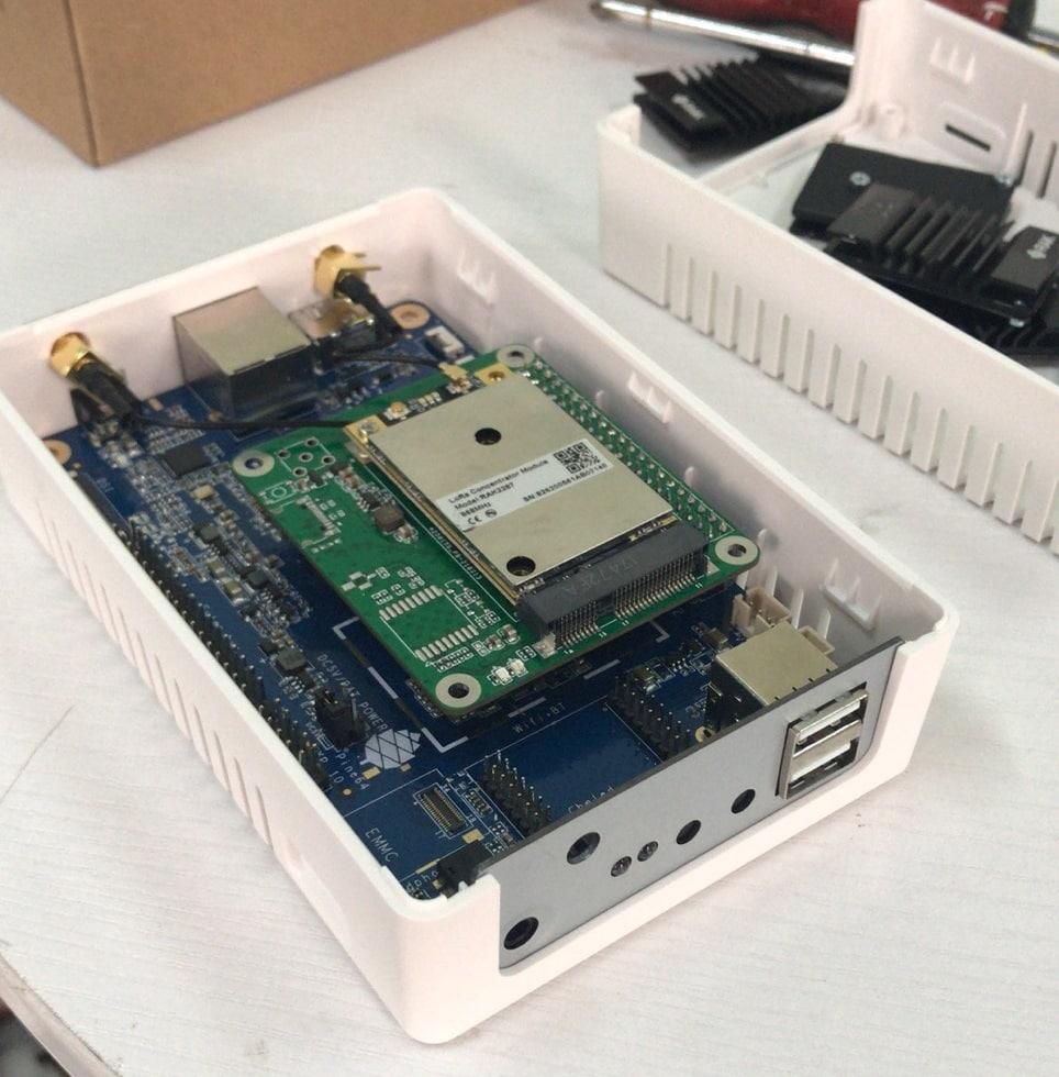
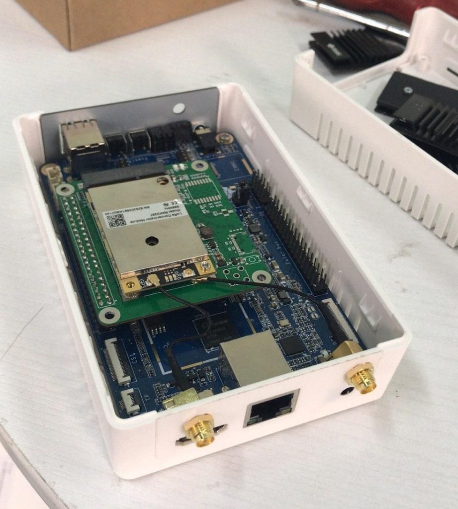
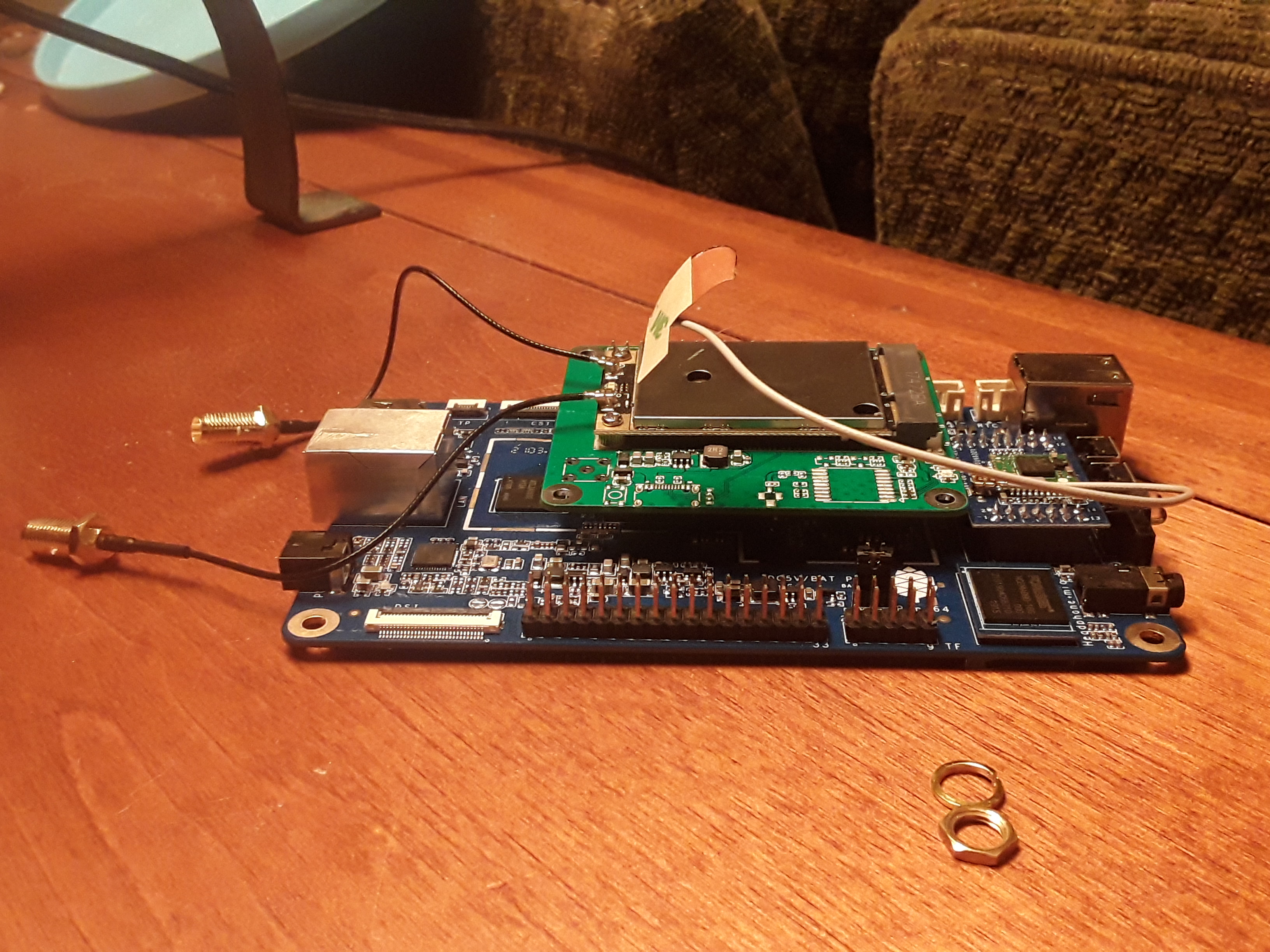
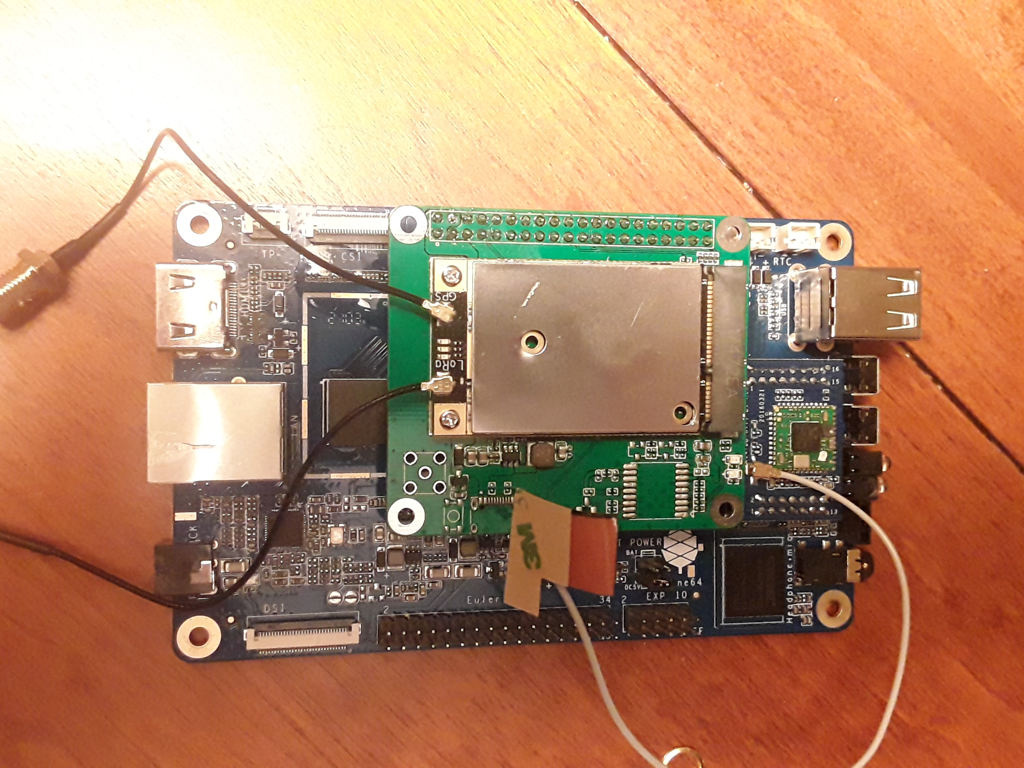
The indoor unit consists of a PINE A64-LTS, fitted with a purpose built hat (adapter) which uses a LoRa module by RakWireless. The chipset used is the SX1303, and the module via the SPI interface. There are two external connections on the enclosure for the GPS and loRa antenna. | |||
=== Connections === | |||
* GPS is connected to UART2 on the A64 board | |||
* SX1303 on SPI0 | |||
{| class="wikitable" | |||
|RAK5146 module | |||
|PI-2 connector | |||
|PINE A64-LTS | |||
|- | |||
|SX1303 SPI | |||
|Pin 19 = MOSI / PC0<br/>Pin 21 = MISO/PC1<br/>Pin23 = CLK/PC2<br/>Pin24 = CS/PC3 | |||
|SPI0 (/dev/spidev0.0) | |||
|- | |||
|SX1303 RESET | |||
|Pin 11 = GPIO17/PC7 | |||
|GPIO71 (/sys/class/gpio/gpio71) | |||
|- | |||
|GPS UART | |||
|Pin 8 = TX/<br>Pin 10 = RX | |||
|UART2 (/dev/ttyS2) | |||
|- | |||
|GPS RESET | |||
|Pin 33 = GPIO13/PC5 | |||
|GPIO69 (/sys/class/gpio/gpio69) | |||
|- | |||
|GPS Standby | |||
|Pin 35 = GPIO19/PC9 | |||
|GPIO73 (/sys/class/gpio/gpio73) | |||
|} | |||
=== Pictures === | |||
<gallery> | |||
File:Blog-april-InsideLoRaGateway.jpg | |||
File:Blog-april-InsideLoRaGateway2.jpeg | |||
File:Discord-lora-gateway-20210413_143615.jpg | |||
File:Discord-lora-gateway-20210413_1435271.jpg | |||
</gallery> | |||
=== Operating systems === | |||
The Pinedio Gateway carries the A64-LTS board. The [[SOPINE Software Releases|SOPINE releases]] are also compatible based on the RAM specifications. | |||
== USB adapter == | |||
[[File:Pine64-lora-usb-adapter.jpg|thumb|right|The PINE64 USB LoRa adapter]] | |||
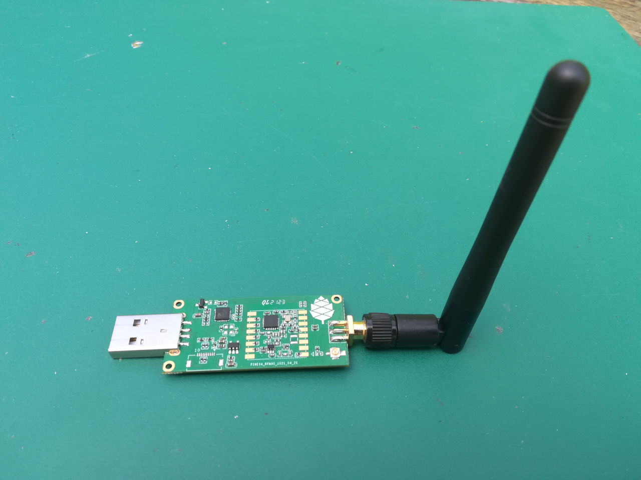
The PINE64 USB LoRa adapter is based on the Semtech SX1262 LoRa module and the CH341 USB bus converter chip. The '''CH341''' chip can be configured in multiple mode to convert USB to various serial and parallel ports. In this case, it's configured in '''synchronous serial mode''', which allows this chip to convert from USB to the SPI bus needed to talk to the SX1262 LoRa module: | |||
-------- -------------------------- | |||
| | | USB LoRa Adapter | | |||
| PC | <--USB--> | CH341 <--SPI--> SX1262 | | |||
| | | <--I/O--> | | |||
-------- -------------------------- | |||
=== Pins === | |||
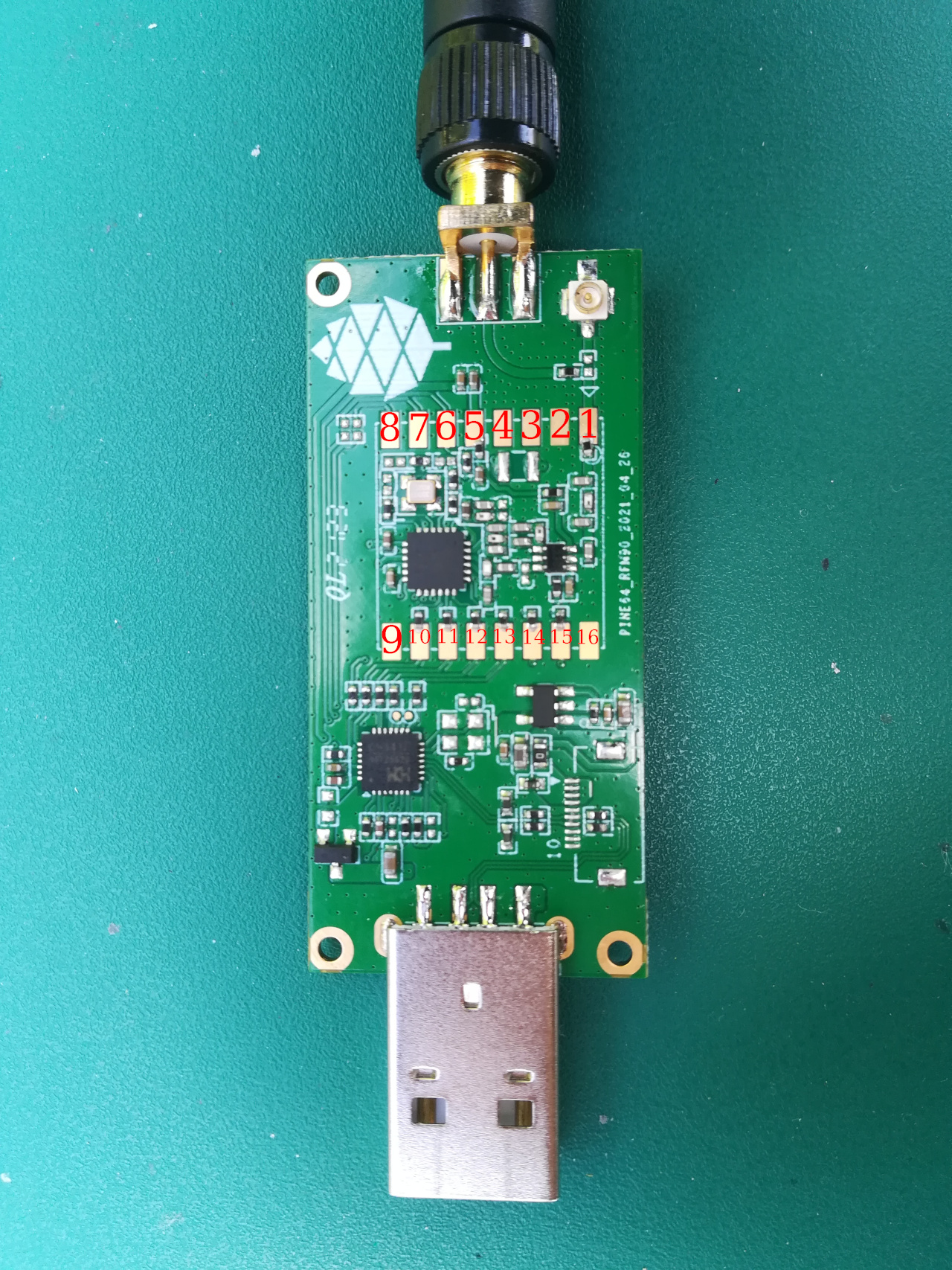
[[File:Lora-usb-pins.jpg|thumb|right|Pinout]] | |||
{|class="wikitable" | |||
!SX1262 Pin | |||
!Name | |||
!Description | |||
|- | |||
|1 | |||
|ANT | |||
|Antenna | |||
|- | |||
|2 | |||
|GND2 | |||
| | |||
|- | |||
|3 | |||
|VREG | |||
| | |||
|- | |||
|4 | |||
|DCC | |||
| | |||
|- | |||
|5 | |||
|VCC | |||
| | |||
|- | |||
|6 | |||
|DIO1 | |||
|Connected on CH341 Pin 7 | |||
|- | |||
|7 | |||
|DIO2 | |||
|Connected on CH341 Pin6 | |||
|- | |||
|8 | |||
|DIO3 | |||
|Connected on CH341 Pin 5 | |||
|- | |||
|9 | |||
|GND | |||
| | |||
|- | |||
|10 | |||
|MISO | |||
|SPI MISO (CH341 Pin 20) | |||
|- | |||
|11 | |||
|MOSI | |||
|SPI MOSI (CH341 Pin 22) | |||
|- | |||
|12 | |||
|SCK | |||
|SPI clock (CH341 Pin 24) | |||
|- | |||
|13 | |||
|NSS | |||
|SPI Chip select | |||
|- | |||
|14 | |||
|POR | |||
|Reset pin | |||
|- | |||
|15 | |||
|Busy | |||
|Busy pin | |||
|- | |||
|16 | |||
|GND | |||
| | |||
|} | |||
=== Kernel module for CH341 === | |||
We need a driver for the CH341 USB bus converter chip. This driver will allow us to send command to the CH341 (SPI messages and access to the GPIOs). I've successfully build and run [https://github.com/rogerjames99/spi-ch341-usb this driver from '''rogerjames99'''] on my desktop computer (running Manjaro Linux) and on my Pinebook Pro (ARM64, running Manjaro ARM Linux). For any kernel newer than 3.10 but mandatory for kernels newer than 5.15 you need to use the [https://github.com/dimich-dmb/spi-ch341-usb dimich-dmb fork of the the '''spi-ch341-usb driver.'''] This fork has updated documentation for the newer kernel interfaces. If this driver gives you problems please drop by any of the social platforms in the Pine64 LoRa chat and give a holler, and if you are using a 5.15 or older kernel you can use the rogerjames99 fork. | |||
$ git clone https://github.com/rogerjames99/spi-ch341-usb.git | |||
or | |||
$ git clone https://github.com/dimich-dmb/spi-ch341-usb.git | |||
then | |||
$ cd spi-ch341-usb | |||
$ make | |||
$ sudo make install | |||
Once the driver is installed, unload the module ''ch341'' if it has been automatically loaded: | |||
$ lsmod |grep ch341 | |||
$ sudo rmmod ch341 | |||
On my setup, ''ch341'' would be automatically loaded once I connected my USB adapter. This module drives the CH341 is asynchronous serial mode, which will not work for a SPI bus. | |||
Then load the new module: | |||
$ sudo modprobe spi-ch341-usb | |||
Plug your USB adapter and check that the module is correctly loaded : | |||
$ dmesg | |||
[20141.872107] usb 1-1.1: USB disconnect, device number 4 | |||
[20143.820756] usb 1-1.1: new full-speed USB device number 5 using ehci-platform | |||
[20143.973366] usb 1-1.1: New USB device found, idVendor=1a86, idProduct=5512, bcdDevice= 3.04 | |||
[20143.973413] usb 1-1.1: New USB device strings: Mfr=0, Product=2, SerialNumber=0 | |||
[20143.973434] usb 1-1.1: Product: USB UART-LPT | |||
[20143.975137] spi-ch341-usb 1-1.1:1.0: ch341_usb_probe: connect device | |||
[20143.975164] spi-ch341-usb 1-1.1:1.0: ch341_usb_probe: bNumEndpoints=3 | |||
[20143.975183] spi-ch341-usb 1-1.1:1.0: ch341_usb_probe: endpoint=0 type=2 dir=1 addr=2 | |||
[20143.975206] spi-ch341-usb 1-1.1:1.0: ch341_usb_probe: endpoint=1 type=2 dir=0 addr=2 | |||
[20143.975229] spi-ch341-usb 1-1.1:1.0: ch341_usb_probe: endpoint=2 type=3 dir=1 addr=1 | |||
[20143.975254] spi-ch341-usb 1-1.1:1.0: ch341_cfg_probe: output cs0 SPI slave with cs=0 | |||
[20143.975273] spi-ch341-usb 1-1.1:1.0: ch341_cfg_probe: output cs0 gpio=0 irq=0 | |||
[20143.975295] spi-ch341-usb 1-1.1:1.0: ch341_cfg_probe: output cs1 SPI slave with cs=1 | |||
[20143.975313] spi-ch341-usb 1-1.1:1.0: ch341_cfg_probe: output cs1 gpio=1 irq=1 | |||
[20143.975334] spi-ch341-usb 1-1.1:1.0: ch341_cfg_probe: output cs2 SPI slave with cs=2 | |||
[20143.975352] spi-ch341-usb 1-1.1:1.0: ch341_cfg_probe: output cs2 gpio=2 irq=2 | |||
[20143.975373] spi-ch341-usb 1-1.1:1.0: ch341_cfg_probe: input gpio4 gpio=3 irq=3 | |||
[20143.975394] spi-ch341-usb 1-1.1:1.0: ch341_cfg_probe: input gpio6 gpio=4 irq=4 | |||
[20143.975415] spi-ch341-usb 1-1.1:1.0: ch341_cfg_probe: input err gpio=5 irq=5 | |||
[20143.975435] spi-ch341-usb 1-1.1:1.0: ch341_cfg_probe: input pemp gpio=6 irq=6 | |||
[20143.975456] spi-ch341-usb 1-1.1:1.0: ch341_cfg_probe: input int gpio=7 irq=7 (hwirq) | |||
[20143.975478] spi-ch341-usb 1-1.1:1.0: ch341_cfg_probe: input slct gpio=8 irq=8 | |||
[20143.975499] spi-ch341-usb 1-1.1:1.0: ch341_cfg_probe: input wait gpio=9 irq=9 | |||
[20143.975520] spi-ch341-usb 1-1.1:1.0: ch341_cfg_probe: input autofd gpio=10 irq=10 | |||
[20143.975542] spi-ch341-usb 1-1.1:1.0: ch341_cfg_probe: input addr gpio=11 irq=11 | |||
[20143.975564] spi-ch341-usb 1-1.1:1.0: ch341_cfg_probe: output ini gpio=12 irq=12 | |||
[20143.975585] spi-ch341-usb 1-1.1:1.0: ch341_cfg_probe: output write gpio=13 irq=13 | |||
[20143.975607] spi-ch341-usb 1-1.1:1.0: ch341_cfg_probe: output scl gpio=14 irq=14 | |||
[20143.975628] spi-ch341-usb 1-1.1:1.0: ch341_cfg_probe: output sda gpio=15 irq=15 | |||
[20143.975650] spi-ch341-usb 1-1.1:1.0: ch341_spi_probe: start | |||
[20143.975677] spi-ch341-usb 1-1.1:1.0: ch341_spi_probe: SPI master connected to SPI bus 1 | |||
[20143.977831] spi-ch341-usb 1-1.1:1.0: ch341_spi_probe: SPI device /dev/spidev1.0 created | |||
[20143.978183] spi-ch341-usb 1-1.1:1.0: ch341_spi_probe: SPI device /dev/spidev1.1 created | |||
[20143.978552] spi-ch341-usb 1-1.1:1.0: ch341_spi_probe: SPI device /dev/spidev1.2 created | |||
[20143.978726] spi-ch341-usb 1-1.1:1.0: ch341_spi_probe: done | |||
[20143.978735] spi-ch341-usb 1-1.1:1.0: ch341_irq_probe: start | |||
[20143.979133] spi-ch341-usb 1-1.1:1.0: ch341_irq_probe: irq_base=103 | |||
[20143.979154] spi-ch341-usb 1-1.1:1.0: ch341_irq_probe: done | |||
[20143.979162] spi-ch341-usb 1-1.1:1.0: ch341_gpio_probe: start | |||
[20143.979220] spi-ch341-usb 1-1.1:1.0: ch341_gpio_get_direction: gpio=cs0 dir=0 | |||
[20143.979229] spi-ch341-usb 1-1.1:1.0: ch341_gpio_get_direction: gpio=cs1 dir=0 | |||
[20143.979237] spi-ch341-usb 1-1.1:1.0: ch341_gpio_get_direction: gpio=cs2 dir=0 | |||
[20143.979245] spi-ch341-usb 1-1.1:1.0: ch341_gpio_get_direction: gpio=gpio4 dir=1 | |||
[20143.979253] spi-ch341-usb 1-1.1:1.0: ch341_gpio_get_direction: gpio=gpio6 dir=1 | |||
[20143.979260] spi-ch341-usb 1-1.1:1.0: ch341_gpio_get_direction: gpio=err dir=1 | |||
[20143.979268] spi-ch341-usb 1-1.1:1.0: ch341_gpio_get_direction: gpio=pemp dir=1 | |||
[20143.979275] spi-ch341-usb 1-1.1:1.0: ch341_gpio_get_direction: gpio=int dir=1 | |||
[20143.979283] spi-ch341-usb 1-1.1:1.0: ch341_gpio_get_direction: gpio=slct dir=1 | |||
[20143.979290] spi-ch341-usb 1-1.1:1.0: ch341_gpio_get_direction: gpio=wait dir=1 | |||
[20143.979298] spi-ch341-usb 1-1.1:1.0: ch341_gpio_get_direction: gpio=autofd dir=1 | |||
[20143.979306] spi-ch341-usb 1-1.1:1.0: ch341_gpio_get_direction: gpio=addr dir=1 | |||
[20143.979314] spi-ch341-usb 1-1.1:1.0: ch341_gpio_get_direction: gpio=ini dir=0 | |||
[20143.979321] spi-ch341-usb 1-1.1:1.0: ch341_gpio_get_direction: gpio=write dir=0 | |||
[20143.979329] spi-ch341-usb 1-1.1:1.0: ch341_gpio_get_direction: gpio=scl dir=0 | |||
[20143.979337] spi-ch341-usb 1-1.1:1.0: ch341_gpio_get_direction: gpio=sda dir=0 | |||
[20143.979831] spi-ch341-usb 1-1.1:1.0: ch341_gpio_probe: registered GPIOs from 496 to 511 | |||
[20143.981152] spi-ch341-usb 1-1.1:1.0: ch341_gpio_probe: done | |||
[20143.981212] spi-ch341-usb 1-1.1:1.0: ch341_gpio_poll_function: start | |||
[20143.981291] spi-ch341-usb 1-1.1:1.0: ch341_usb_probe: connected | |||
[20144.756250] usbcore: registered new interface driver ch341 | |||
[20144.756334] usbserial: USB Serial support registered for ch341-uart | |||
With kernel 5.16 and newer the output is shorter: | |||
$ dmesg | |||
[ 6744.813564] usb 1-2.1.1: new full-speed USB device number 21 using xhci_hcd | |||
[ 6744.904377] usb 1-2.1.1: New USB device found, idVendor=1a86, idProduct=5512, bcdDevice= 3.04 | |||
[ 6744.904383] usb 1-2.1.1: New USB device strings: Mfr=0, Product=2, SerialNumber=0 | |||
[ 6744.904385] usb 1-2.1.1: Product: USB UART-LPT | |||
[ 6744.960243] spi-ch341-usb 1-2.1.1:1.0: ch341_cfg_probe: output cs0 SPI slave with cs=0 | |||
[ 6744.960246] spi-ch341-usb 1-2.1.1:1.0: ch341_cfg_probe: output cs1 SPI slave with cs=1 | |||
[ 6744.960247] spi-ch341-usb 1-2.1.1:1.0: ch341_cfg_probe: output cs2 SPI slave with cs=2 | |||
[ 6744.960249] spi-ch341-usb 1-2.1.1:1.0: ch341_cfg_probe: input gpio4 gpio=0 irq=0 (hwirq) | |||
[ 6744.960251] spi-ch341-usb 1-2.1.1:1.0: ch341_cfg_probe: input gpio5 gpio=1 irq=1 | |||
[ 6744.960302] spi-ch341-usb 1-2.1.1:1.0: ch341_spi_probe: SPI master connected to SPI bus 0 | |||
[ 6744.960350] spi-ch341-usb 1-2.1.1:1.0: ch341_spi_probe: SPI device /dev/spidev0.0 created | |||
[ 6744.960398] spi-ch341-usb 1-2.1.1:1.0: ch341_spi_probe: SPI device /dev/spidev0.1 created | |||
[ 6744.960445] spi-ch341-usb 1-2.1.1:1.0: ch341_spi_probe: SPI device /dev/spidev0.2 created | |||
[ 6744.960583] spi-ch341-usb 1-2.1.1:1.0: ch341_usb_probe: connected | |||
=== Driver development === | |||
==== Kernels 5.14 and older ==== | |||
Once the module ''spi-ch341-usb'' is correctly loaded, here's how you can transfer data on the SPI bus (in C): | |||
/* Open the SPI bus */ | |||
int spi = open("/dev/spidev1.0", O_RDWR); | |||
uint8_t mmode = SPI_MODE_0; | |||
uint8_t lsb = 0; | |||
ioctl(spi, SPI_IOC_WR_MODE, &mmode); | |||
ioctl(spi, SPI_IOC_WR_LSB_FIRST, &lsb); | |||
/* Transfer data */ | |||
/* TODO: Init buffer_out, buffer_in and size */ | |||
const uint8_t *mosi = buffer_out; // output data | |||
uint8_t *miso = buffer_in; // input data | |||
struct spi_ioc_transfer spi_trans; | |||
memset(&spi_trans, 0, sizeof(spi_trans)); | |||
spi_trans.tx_buf = (unsigned long) mosi; | |||
spi_trans.rx_buf = (unsigned long) miso; | |||
spi_trans.cs_change = true; | |||
spi_trans.len = size; | |||
int status = ioctl (spi, SPI_IOC_MESSAGE(1), &spi_trans); | |||
To access GPIOs, you first need to export them (to make them accessible via ''/sys/class/gpio''. As you can see in the dmesg output, GPIOs from 496 to 511 were registered, which means we can export 16 GPIOs. The mapping of these I/O is available in the [https://github.com/rogerjames99/spi-ch341-usb/blob/master/spi-ch341-usb.c#L148 source code of the driver]. For example, pin ''slct'' is the 12th, meaning we need to export GPIO 496+12 = 508. | |||
int fd; | |||
if ((fd = open("/sys/class/gpio/export", O_WRONLY)) == -1) { | |||
perror("open ini"); | |||
exit(-1); | |||
} | |||
if (write(fd, "508", 3) == -1){ | |||
perror ("write export 508"); | |||
} | |||
Once exported, the GPIO is available in ''/sys/class/gpio/sclt'' (the naming is specified by the driver). You can read the pin in C: | |||
int fd; | |||
if ((fd = open("/sys/class/gpio/slct/value", O_RDWR)) == -1) { | |||
perror("open"); | |||
} | |||
char buf; | |||
if (read(fd, &buf, 1) == -1) { | |||
perror("read"); | |||
} | |||
int value = (buf == '0') ? 0 : 1; | |||
You can also write it: | |||
int fd; | |||
if ((fd = open("/sys/class/gpio/ini/value", O_RDWR)) == -1) { | |||
perror("open ini"); | |||
} | |||
if (write(fd, value ? "1" : "0", 1) == -1) { | |||
perror ("write"); | |||
} | |||
==== Kernel 5.15 and newer ==== | |||
We need some help documenting how these interfaces work! | |||
The driver creates these interfaces: | |||
{| class="wikitable" | |||
! Pin !! SPI Function !! GPIO function !! GPIO name !! IRQ | |||
|- | |||
| 15 || CS0 || - || - || - | |||
|- | |||
| 16 || CS1 || - || - || - | |||
|- | |||
| 17 || CS2 || - || - || - | |||
|- | |||
| 19 || - || Input || gpio4 || hardware | |||
|- | |||
| 21 || - || Input || gpio5 || software | |||
|} | |||
The dimich-dmb fork of spi-ch341-usb works with 5.15+ kernels, but as you can see above it is not configured for the needs of the Pinedio-USB by default. I have started a branch in my fork to work on getting the driver pre-configured for our needs. The branch can be [https://github.com/UncleGrumpy/spi-ch341-usb/tree/pinedio found here.] Please feel free to help! And open issues or discussions in the repo if you have problems or ideas how to help. Any improvements to the actual code beyond configuration should be pushed to the temporary [https://github.com/dimich-dmb/spi-ch341-usb/ upstream.] | |||
Since linux-5.15 binding to spidev driver is required to make slave devices available via /dev/, e.g. for slave 1 on bus 0 as real root (not with sudo): | |||
# echo spidev > /sys/class/spi_master/spi0/spi0.1/driver_override | |||
# echo spi0.1 > /sys/bus/spi/drivers/spidev/bind | |||
For all devices handled by spi_ch341_usb driver (again, only as real root): | |||
# for i in /sys/bus/usb/drivers/spi-ch341-usb/*/spi_master/spi*/spi*.*; do echo spidev > $i/driver_override; echo $(basename $i) > /sys/bus/spi/drivers/spidev/bind; done | |||
The documentation found at https://github.com/dimich-dmb/spi-ch341-usb/blob/master/README.md has more information. | |||
The 5.15+ driver is not ready yet. But if you are interested in testing, helping to get the configuration right, or working on application development you can build and test the current driver: | |||
$ git clone -b pinedio https://github.com/UncleGrumpy/spi-ch341-usb.git | |||
$ cd spi-ch341-usb | |||
$ make | |||
$ sudo make install | |||
So far this will automatically set up the SPI slave device /dev/spi0.0. It names the ch341-usb device as "pinedio" this will allow application developers to find the correct gpiochip by name. I need help confirming the correct gpio pins but as of now the driver will setup the following configuration: | |||
The driver uses following CH341A pins for the SPI interface. | |||
{| class="wikitable" | |||
| Pin || Name || Direction || Function SPI (CH341A) | |||
|- | |||
| 18 || D3 || output || SCK (DCK) | |||
|- | |||
| 20 || D5 || output || MOSI (DOUT) | |||
|- | |||
| 22 || D7 || input || MISO (DIN) | |||
|- | |||
| 15 || D0 || output || CS0 | |||
|} | |||
The driver uses the following GPIO configuration. | |||
{{Warning|It is not sure if these are the correct pins to use!}} | |||
{| class="wikitable" | |||
| CH341 Pin || CH341A Name || Function || GPIO Name || GPIO Configuration || SX1262 connection | |||
|- | |||
| 7 || INT# || IRQ || dio_irq || Output || DIO1 (IRQ) | |||
|- | |||
| 8 || SLCT || BUSY || dio_busy || Input || BUSY | |||
|- | |||
| 26 || RST# || Hard Reset || dio_reset || Output || NRESET | |||
|} | |||
The function of these pins can be changed from user space by using libgpiod. The command line tools installed with the library (gpioset, gpioget, gpiodetect, gpioinfo...) can be used for bash scripts, etc. and applications should all use the libgpiod interfaces. The /sys/class/gpio interface has been removed from the kernel in 5.15, so any apps using /sys/class/gpio to access gpio pins are broken, or will be as distos update their kernels to 5.15 and beyond. | |||
GPIO pins can be listed with gpioinfo: | |||
$ gpioinfo pinedio | |||
The output should look similar to: | |||
gpiochip1 - 3 lines: | |||
line 0: "dio_irq" unused input active-high | |||
line 1: "dio_busy" unused input active-high | |||
line 2: "dio_reset" unused output active-high | |||
The gpiochip# might be different. The driver exposes the Pinedio with the gpio name "pinedio", developers should use this name to interact with the gpiochip because the gpiochip# of the device is likely to be different from one system to the next, or depending on the order devices are initialized. | |||
=== Driver for the SX1262 LoRa module === | |||
Now that we can talk to the SX1262 via the CH341 USB converter chip, we need to send actual commands to make it emit or receive LoRa messages. To do this, you can implement the driver yourself using info from the datasheet, or use an existing driver (you can easily find drivers for the Arduino framework, for example. | |||
I found [https://github.com/YukiWorkshop/sx126x_driver this C++ driver]. It's well written, lightweight and easily portable across many platforms. All you have to do is implement 3 HAL function : read GPIO, write GPIO and transfer data on SPI. I wrote a quick'n'dirty app that emits a LoRa frame. It's [https://gist.github.com/JF002/f1af5595874942427eea9d375c18fc73 available here]. | |||
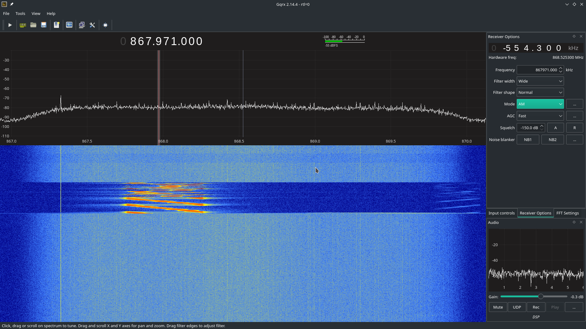
As I don't have any 'raw' LoRa device on hands, I check that it was actually transmitting something using my SDR setup (simple TNT usb key and '''Gqrx''' software): | |||
[[File:pine64-lora-usb-adapter-sdr.png|500px]] | |||
== Other end nodes == | |||
There are several end-node units planned: | |||
* loRa back case for the PinePhone | |||
* standalone USB dongle-type end-node adapter | |||
* PineTab adapter | |||
* as well as a SPI module (which can also be configured as a USB LoRa dongle) | |||
* a LoRa stick powered by a single 18650 battery (using the [https://wiki.pine64.org/wiki/Nutcracker BL602], and can be fitted with GPS, an low-power OLED panel and additional sensors) | |||
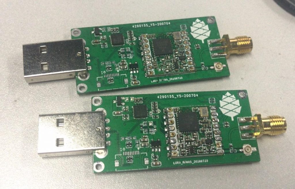
All the end-nodes use the SX1262 chip. | |||
=== Pictures === | |||
<gallery> | |||
File:Blog-april-USB-LoRa-1024x655.jpg | |||
File:Blog-april-LoRa-something-839x1024.jpg | |||
File:Discord_20210421_lora_usb_closeup.jpg | |||
</gallery> | |||
== Datasheets and schematics == | == Datasheets and schematics == | ||
=== Gateway === | |||
* [https://semtech.my.salesforce.com/sfc/p/#E0000000JelG/a/2R000000Hlli/Te0cB6.fNWAPfxRfoFz38R6LOTf3sLAJhD4CpS2RwFc SX1303 datasheets and resources] | |||
* [https://docs.rakwireless.com/Product-Categories/WisLink/RAK5146/Datasheet/#overview RAK5146 datasheets and resources] | |||
* [[File:PINE64_LoRa_Gateway_Module_Adapter_Schematic-v1.0-20210308.pdf|Pine64 LoRa Gateway module adapter schematic]] | |||
=== End nodes === | |||
* [https://www.semtech.com/products/wireless-rf/lora-transceivers/sx1262 SX1262 datasheets and resources] | |||
=== Pinephone backplate === | === Pinephone backplate === | ||
* [[File:Pinephone_LoRa_BackPanel_Schematic-v1.0-20210402.pdf]] | * [[File:Pinephone_LoRa_BackPanel_Schematic-v1.0-20210402.pdf]] | ||
* [[File:CA-S01_LoRa_Chip_Antenna_in_Chinese.pdf]] | * [[File:CA-S01_LoRa_Chip_Antenna_in_Chinese.pdf]] | ||
* [https://github.com/zschroeder6212/tiny-i2c-spi I2C SPI Bridge code running on ATtiny84] | |||
=== USB LoRa adapter === | |||
* [[File:USB_LoRa_adapter-PINE64_RFM90_SCH_2021_04_26.pdf]] | |||
* CH341 datasheet : [[File:CH341DS1.pdf]] | |||
* Semtech SX1262 datasheet : [https://semtech.my.salesforce.com/sfc/p/#E0000000JelG/a/2R000000HT76/7Nka9W5WgugoZe.xwIHJy6ebj1hW8UJ.USO_Pt2CLLo File on Semtech website (file is too big for the wiki)] | |||
=== PineDio Stack === | |||
* Schematic: [[File:PINEDIO_STACK_V1_0-2021_05_24C.pdf]] | |||
== Other resources == | |||
* [https://www.youtube.com/watch?v=cJ0wpANpbyc Video: A peek at Pine64's LoRa gateway and modules] | |||
* [https://iotw.io/ IOTW - Blockchain-Enabled IoT Data Platform] | |||
* [https://lupyuen.github.io/articles/pinedio PineDio Stack BL604 RISC-V Board: Testing The Prototype] | |||
* [https://lupyuen.github.io/articles/lorawan2 LoRaWAN on PineDio Stack BL604 RISC-V Board] | |||
* [https://lupyuen.github.io/articles/ttn The Things Network on PineDio Stack BL604 RISC-V Board] | |||
* [https://lupyuen.github.io/articles/prometheus Monitor IoT Devices in The Things Network with Prometheus and Grafana] | |||
* [https://lupyuen.github.io/articles/tsen Internal Temperature Sensor on BL602] | |||
* [https://lupyuen.github.io/articles/roblox IoT Digital Twin with Roblox and The Things Network] | |||
* [https://lupyuen.github.io/articles/gateway PineDio LoRa Gateway: Testing The Prototype] | |||
* [https://lupyuen.github.io/articles/nuttx Apache NuttX OS on RISC-V BL602 and BL604] | |||
* [https://lupyuen.github.io/articles/spi2 SPI on Apache NuttX OS] | |||
* [https://lupyuen.github.io/articles/sx1262 LoRa SX1262 on Apache NuttX OS] | |||
* [https://lupyuen.github.io/articles/lorawan3 LoRaWAN on Apache NuttX OS] | |||
* [https://lupyuen.github.io/articles/rust2 Rust on Apache NuttX OS] | |||
* [https://lupyuen.github.io/articles/ikea Connect IKEA Air Quality Sensor to Apache NuttX OS] | |||
* [https://lupyuen.github.io/articles/pinedio2 PineDio Stack BL604 runs Apache NuttX RTOS] | |||
* [https://lupyuen.github.io/articles/touch NuttX Touch Panel Driver for PineDio Stack BL604] | |||
* [https://www.robertlipe.com/buttons-on-bl602-nuttx/ Buttons on BL602 NuttX] | |||
* [https://lupyuen.github.io/articles/expander NuttX GPIO Expander for PineDio Stack BL604] | |||
* [https://lupyuen.github.io/articles/auto2 (Mostly) Automated Testing of Apache NuttX RTOS on PineDio Stack BL604 RISC-V Board] | |||
* [https://lupyuen.github.io/articles/zig Zig on RISC-V BL602: Quick Peek with Apache NuttX RTOS] | |||
* [https://lupyuen.github.io/articles/iot Build an IoT App with Zig and LoRaWAN] | |||
* [https://lupyuen.github.io/articles/lvgl Build an LVGL Touchscreen App with Zig] | |||
* [https://youtu.be/_vADRu939sI Apache NuttX RTOS on a RISC-V IoT Gadget: PineDio Stack BL604 (Video)] | |||
* [https://youtu.be/-2OIHur8X1E Simpler, safer LVGL Touchscreen Apps with Zig and Apache NuttX RTOS (Video)] | |||
[[Category:Pinedio]] | |||
Latest revision as of 15:38, 5 April 2023
The Pinedio is a device utilizing LoRa. LoRa is a long range, low power wireless platform that is being used by a lot of Internet of Things (IoT) products. Using LoRa and LoRaWAN, devices can communicate across the world using the internet, using various decentralised networks such as The Things Network or Helium. Since, PINE64 believes in openness, the LoRa gateway can connect to any network, per the developer implementation. If Helium Spots open up for PINE64 gateway and developers have implemented the hook for Helium, then this is good thing. The PINE64 LoRa gateway also open connect to The Things Network if developers implement support. The choice is yours!
Gateway
The gateway will be available in two variants - indoor and outdoor. All that is known about the outdoor unit is that it will have "an aluminum, rugged and water resistant case". The indoor unit consists of a PINE A64-LTS, fitted with a purpose built hat (adapter) which uses a LoRa module by RakWireless. The chipset used is the SX1303, and the module via the SPI interface. There are two external connections on the enclosure for the GPS and loRa antenna.
Connections
- GPS is connected to UART2 on the A64 board
- SX1303 on SPI0
| RAK5146 module | PI-2 connector | PINE A64-LTS |
| SX1303 SPI | Pin 19 = MOSI / PC0 Pin 21 = MISO/PC1 Pin23 = CLK/PC2 Pin24 = CS/PC3 |
SPI0 (/dev/spidev0.0) |
| SX1303 RESET | Pin 11 = GPIO17/PC7 | GPIO71 (/sys/class/gpio/gpio71) |
| GPS UART | Pin 8 = TX/ Pin 10 = RX |
UART2 (/dev/ttyS2) |
| GPS RESET | Pin 33 = GPIO13/PC5 | GPIO69 (/sys/class/gpio/gpio69) |
| GPS Standby | Pin 35 = GPIO19/PC9 | GPIO73 (/sys/class/gpio/gpio73) |
Pictures
Operating systems
The Pinedio Gateway carries the A64-LTS board. The SOPINE releases are also compatible based on the RAM specifications.
USB adapter
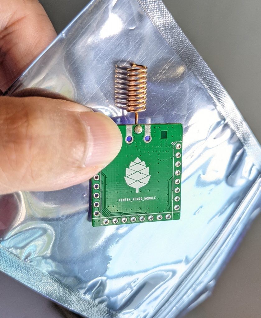
The PINE64 USB LoRa adapter is based on the Semtech SX1262 LoRa module and the CH341 USB bus converter chip. The CH341 chip can be configured in multiple mode to convert USB to various serial and parallel ports. In this case, it's configured in synchronous serial mode, which allows this chip to convert from USB to the SPI bus needed to talk to the SX1262 LoRa module:
--------            --------------------------
|      |            |   USB LoRa Adapter     |
| PC   |  <--USB--> | CH341 <--SPI--> SX1262 |
|      |            |       <--I/O-->        |
--------            --------------------------
Pins
| SX1262 Pin | Name | Description |
|---|---|---|
| 1 | ANT | Antenna |
| 2 | GND2 | |
| 3 | VREG | |
| 4 | DCC | |
| 5 | VCC | |
| 6 | DIO1 | Connected on CH341 Pin 7 |
| 7 | DIO2 | Connected on CH341 Pin6 |
| 8 | DIO3 | Connected on CH341 Pin 5 |
| 9 | GND | |
| 10 | MISO | SPI MISO (CH341 Pin 20) |
| 11 | MOSI | SPI MOSI (CH341 Pin 22) |
| 12 | SCK | SPI clock (CH341 Pin 24) |
| 13 | NSS | SPI Chip select |
| 14 | POR | Reset pin |
| 15 | Busy | Busy pin |
| 16 | GND |
Kernel module for CH341
We need a driver for the CH341 USB bus converter chip. This driver will allow us to send command to the CH341 (SPI messages and access to the GPIOs). I've successfully build and run this driver from rogerjames99 on my desktop computer (running Manjaro Linux) and on my Pinebook Pro (ARM64, running Manjaro ARM Linux). For any kernel newer than 3.10 but mandatory for kernels newer than 5.15 you need to use the dimich-dmb fork of the the spi-ch341-usb driver. This fork has updated documentation for the newer kernel interfaces. If this driver gives you problems please drop by any of the social platforms in the Pine64 LoRa chat and give a holler, and if you are using a 5.15 or older kernel you can use the rogerjames99 fork.
$ git clone https://github.com/rogerjames99/spi-ch341-usb.git
or
$ git clone https://github.com/dimich-dmb/spi-ch341-usb.git
then
$ cd spi-ch341-usb
$ make
$ sudo make install
Once the driver is installed, unload the module ch341 if it has been automatically loaded:
$ lsmod |grep ch341
$ sudo rmmod ch341
On my setup, ch341 would be automatically loaded once I connected my USB adapter. This module drives the CH341 is asynchronous serial mode, which will not work for a SPI bus.
Then load the new module:
$ sudo modprobe spi-ch341-usb
Plug your USB adapter and check that the module is correctly loaded :
$ dmesg
[20141.872107] usb 1-1.1: USB disconnect, device number 4
[20143.820756] usb 1-1.1: new full-speed USB device number 5 using ehci-platform
[20143.973366] usb 1-1.1: New USB device found, idVendor=1a86, idProduct=5512, bcdDevice= 3.04
[20143.973413] usb 1-1.1: New USB device strings: Mfr=0, Product=2, SerialNumber=0
[20143.973434] usb 1-1.1: Product: USB UART-LPT
[20143.975137] spi-ch341-usb 1-1.1:1.0: ch341_usb_probe: connect device
[20143.975164] spi-ch341-usb 1-1.1:1.0: ch341_usb_probe: bNumEndpoints=3
[20143.975183] spi-ch341-usb 1-1.1:1.0: ch341_usb_probe:   endpoint=0 type=2 dir=1 addr=2
[20143.975206] spi-ch341-usb 1-1.1:1.0: ch341_usb_probe:   endpoint=1 type=2 dir=0 addr=2
[20143.975229] spi-ch341-usb 1-1.1:1.0: ch341_usb_probe:   endpoint=2 type=3 dir=1 addr=1
[20143.975254] spi-ch341-usb 1-1.1:1.0: ch341_cfg_probe: output cs0 SPI slave with cs=0
[20143.975273] spi-ch341-usb 1-1.1:1.0: ch341_cfg_probe: output cs0 gpio=0 irq=0
[20143.975295] spi-ch341-usb 1-1.1:1.0: ch341_cfg_probe: output cs1 SPI slave with cs=1
[20143.975313] spi-ch341-usb 1-1.1:1.0: ch341_cfg_probe: output cs1 gpio=1 irq=1
[20143.975334] spi-ch341-usb 1-1.1:1.0: ch341_cfg_probe: output cs2 SPI slave with cs=2
[20143.975352] spi-ch341-usb 1-1.1:1.0: ch341_cfg_probe: output cs2 gpio=2 irq=2
[20143.975373] spi-ch341-usb 1-1.1:1.0: ch341_cfg_probe: input  gpio4 gpio=3 irq=3
[20143.975394] spi-ch341-usb 1-1.1:1.0: ch341_cfg_probe: input  gpio6 gpio=4 irq=4
[20143.975415] spi-ch341-usb 1-1.1:1.0: ch341_cfg_probe: input  err gpio=5 irq=5
[20143.975435] spi-ch341-usb 1-1.1:1.0: ch341_cfg_probe: input  pemp gpio=6 irq=6
[20143.975456] spi-ch341-usb 1-1.1:1.0: ch341_cfg_probe: input  int gpio=7 irq=7 (hwirq)
[20143.975478] spi-ch341-usb 1-1.1:1.0: ch341_cfg_probe: input  slct gpio=8 irq=8
[20143.975499] spi-ch341-usb 1-1.1:1.0: ch341_cfg_probe: input  wait gpio=9 irq=9
[20143.975520] spi-ch341-usb 1-1.1:1.0: ch341_cfg_probe: input  autofd gpio=10 irq=10
[20143.975542] spi-ch341-usb 1-1.1:1.0: ch341_cfg_probe: input  addr gpio=11 irq=11
[20143.975564] spi-ch341-usb 1-1.1:1.0: ch341_cfg_probe: output ini gpio=12 irq=12
[20143.975585] spi-ch341-usb 1-1.1:1.0: ch341_cfg_probe: output write gpio=13 irq=13
[20143.975607] spi-ch341-usb 1-1.1:1.0: ch341_cfg_probe: output scl gpio=14 irq=14
[20143.975628] spi-ch341-usb 1-1.1:1.0: ch341_cfg_probe: output sda gpio=15 irq=15
[20143.975650] spi-ch341-usb 1-1.1:1.0: ch341_spi_probe: start
[20143.975677] spi-ch341-usb 1-1.1:1.0: ch341_spi_probe: SPI master connected to SPI bus 1
[20143.977831] spi-ch341-usb 1-1.1:1.0: ch341_spi_probe: SPI device /dev/spidev1.0 created
[20143.978183] spi-ch341-usb 1-1.1:1.0: ch341_spi_probe: SPI device /dev/spidev1.1 created
[20143.978552] spi-ch341-usb 1-1.1:1.0: ch341_spi_probe: SPI device /dev/spidev1.2 created
[20143.978726] spi-ch341-usb 1-1.1:1.0: ch341_spi_probe: done
[20143.978735] spi-ch341-usb 1-1.1:1.0: ch341_irq_probe: start
[20143.979133] spi-ch341-usb 1-1.1:1.0: ch341_irq_probe: irq_base=103
[20143.979154] spi-ch341-usb 1-1.1:1.0: ch341_irq_probe: done
[20143.979162] spi-ch341-usb 1-1.1:1.0: ch341_gpio_probe: start
[20143.979220] spi-ch341-usb 1-1.1:1.0: ch341_gpio_get_direction: gpio=cs0 dir=0
[20143.979229] spi-ch341-usb 1-1.1:1.0: ch341_gpio_get_direction: gpio=cs1 dir=0
[20143.979237] spi-ch341-usb 1-1.1:1.0: ch341_gpio_get_direction: gpio=cs2 dir=0
[20143.979245] spi-ch341-usb 1-1.1:1.0: ch341_gpio_get_direction: gpio=gpio4 dir=1
[20143.979253] spi-ch341-usb 1-1.1:1.0: ch341_gpio_get_direction: gpio=gpio6 dir=1
[20143.979260] spi-ch341-usb 1-1.1:1.0: ch341_gpio_get_direction: gpio=err dir=1
[20143.979268] spi-ch341-usb 1-1.1:1.0: ch341_gpio_get_direction: gpio=pemp dir=1
[20143.979275] spi-ch341-usb 1-1.1:1.0: ch341_gpio_get_direction: gpio=int dir=1
[20143.979283] spi-ch341-usb 1-1.1:1.0: ch341_gpio_get_direction: gpio=slct dir=1
[20143.979290] spi-ch341-usb 1-1.1:1.0: ch341_gpio_get_direction: gpio=wait dir=1
[20143.979298] spi-ch341-usb 1-1.1:1.0: ch341_gpio_get_direction: gpio=autofd dir=1
[20143.979306] spi-ch341-usb 1-1.1:1.0: ch341_gpio_get_direction: gpio=addr dir=1
[20143.979314] spi-ch341-usb 1-1.1:1.0: ch341_gpio_get_direction: gpio=ini dir=0
[20143.979321] spi-ch341-usb 1-1.1:1.0: ch341_gpio_get_direction: gpio=write dir=0
[20143.979329] spi-ch341-usb 1-1.1:1.0: ch341_gpio_get_direction: gpio=scl dir=0
[20143.979337] spi-ch341-usb 1-1.1:1.0: ch341_gpio_get_direction: gpio=sda dir=0
[20143.979831] spi-ch341-usb 1-1.1:1.0: ch341_gpio_probe: registered GPIOs from 496 to 511
[20143.981152] spi-ch341-usb 1-1.1:1.0: ch341_gpio_probe: done
[20143.981212] spi-ch341-usb 1-1.1:1.0: ch341_gpio_poll_function: start
[20143.981291] spi-ch341-usb 1-1.1:1.0: ch341_usb_probe: connected
[20144.756250] usbcore: registered new interface driver ch341
[20144.756334] usbserial: USB Serial support registered for ch341-uart
With kernel 5.16 and newer the output is shorter:
$ dmesg
[ 6744.813564] usb 1-2.1.1: new full-speed USB device number 21 using xhci_hcd
[ 6744.904377] usb 1-2.1.1: New USB device found, idVendor=1a86, idProduct=5512, bcdDevice= 3.04
[ 6744.904383] usb 1-2.1.1: New USB device strings: Mfr=0, Product=2, SerialNumber=0
[ 6744.904385] usb 1-2.1.1: Product: USB UART-LPT
[ 6744.960243] spi-ch341-usb 1-2.1.1:1.0: ch341_cfg_probe: output cs0 SPI slave with cs=0
[ 6744.960246] spi-ch341-usb 1-2.1.1:1.0: ch341_cfg_probe: output cs1 SPI slave with cs=1
[ 6744.960247] spi-ch341-usb 1-2.1.1:1.0: ch341_cfg_probe: output cs2 SPI slave with cs=2
[ 6744.960249] spi-ch341-usb 1-2.1.1:1.0: ch341_cfg_probe: input  gpio4 gpio=0 irq=0 (hwirq)
[ 6744.960251] spi-ch341-usb 1-2.1.1:1.0: ch341_cfg_probe: input  gpio5 gpio=1 irq=1
[ 6744.960302] spi-ch341-usb 1-2.1.1:1.0: ch341_spi_probe: SPI master connected to SPI bus 0
[ 6744.960350] spi-ch341-usb 1-2.1.1:1.0: ch341_spi_probe: SPI device /dev/spidev0.0 created
[ 6744.960398] spi-ch341-usb 1-2.1.1:1.0: ch341_spi_probe: SPI device /dev/spidev0.1 created
[ 6744.960445] spi-ch341-usb 1-2.1.1:1.0: ch341_spi_probe: SPI device /dev/spidev0.2 created
[ 6744.960583] spi-ch341-usb 1-2.1.1:1.0: ch341_usb_probe: connected
Driver development
Kernels 5.14 and older
Once the module spi-ch341-usb is correctly loaded, here's how you can transfer data on the SPI bus (in C):
/* Open the SPI bus */
int spi = open("/dev/spidev1.0", O_RDWR);
uint8_t mmode = SPI_MODE_0;
uint8_t lsb = 0;
ioctl(spi, SPI_IOC_WR_MODE, &mmode);
ioctl(spi, SPI_IOC_WR_LSB_FIRST, &lsb);

/* Transfer data */
/* TODO: Init buffer_out, buffer_in and size */
const uint8_t *mosi = buffer_out; // output data
uint8_t *miso = buffer_in; // input data

struct spi_ioc_transfer spi_trans;
memset(&spi_trans, 0, sizeof(spi_trans));

spi_trans.tx_buf = (unsigned long) mosi;
spi_trans.rx_buf = (unsigned long) miso;
spi_trans.cs_change = true;
spi_trans.len = size;

int status = ioctl (spi, SPI_IOC_MESSAGE(1), &spi_trans);
To access GPIOs, you first need to export them (to make them accessible via /sys/class/gpio. As you can see in the dmesg output, GPIOs from 496 to 511 were registered, which means we can export 16 GPIOs. The mapping of these I/O is available in the source code of the driver. For example, pin slct is the 12th, meaning we need to export GPIO 496+12 = 508.
int  fd;
if ((fd = open("/sys/class/gpio/export", O_WRONLY)) == -1)   {
  perror("open ini");
  exit(-1);
}

if (write(fd, "508", 3) == -1){
  perror ("write export 508");
}
Once exported, the GPIO is available in /sys/class/gpio/sclt (the naming is specified by the driver). You can read the pin in C:
int  fd;
if ((fd = open("/sys/class/gpio/slct/value", O_RDWR)) == -1)   {
  perror("open");
}

char buf;
if (read(fd, &buf, 1) == -1) {
   perror("read");
}

int value = (buf == '0') ? 0 : 1;
You can also write it:
int  fd;
if ((fd = open("/sys/class/gpio/ini/value", O_RDWR)) == -1)   {
  perror("open ini");
}

if (write(fd, value ? "1" : "0", 1) == -1) {
   perror ("write");
}
Kernel 5.15 and newer
We need some help documenting how these interfaces work!
The driver creates these interfaces:
| Pin | SPI Function | GPIO function | GPIO name | IRQ |
|---|---|---|---|---|
| 15 | CS0 | - | - | - |
| 16 | CS1 | - | - | - |
| 17 | CS2 | - | - | - |
| 19 | - | Input | gpio4 | hardware |
| 21 | - | Input | gpio5 | software |
The dimich-dmb fork of spi-ch341-usb works with 5.15+ kernels, but as you can see above it is not configured for the needs of the Pinedio-USB by default. I have started a branch in my fork to work on getting the driver pre-configured for our needs. The branch can be found here. Please feel free to help! And open issues or discussions in the repo if you have problems or ideas how to help. Any improvements to the actual code beyond configuration should be pushed to the temporary upstream.
Since linux-5.15 binding to spidev driver is required to make slave devices available via /dev/, e.g. for slave 1 on bus 0 as real root (not with sudo):
# echo spidev > /sys/class/spi_master/spi0/spi0.1/driver_override
# echo spi0.1 > /sys/bus/spi/drivers/spidev/bind
For all devices handled by spi_ch341_usb driver (again, only as real root):
# for i in /sys/bus/usb/drivers/spi-ch341-usb/*/spi_master/spi*/spi*.*; do echo spidev > $i/driver_override; echo $(basename $i) > /sys/bus/spi/drivers/spidev/bind; done
The documentation found at https://github.com/dimich-dmb/spi-ch341-usb/blob/master/README.md has more information.
The 5.15+ driver is not ready yet. But if you are interested in testing, helping to get the configuration right, or working on application development you can build and test the current driver:
$ git clone -b pinedio https://github.com/UncleGrumpy/spi-ch341-usb.git
$ cd spi-ch341-usb
$ make
$ sudo make install
So far this will automatically set up the SPI slave device /dev/spi0.0. It names the ch341-usb device as "pinedio" this will allow application developers to find the correct gpiochip by name. I need help confirming the correct gpio pins but as of now the driver will setup the following configuration:
The driver uses following CH341A pins for the SPI interface.
| Pin | Name | Direction | Function SPI (CH341A) |
| 18 | D3 | output | SCK (DCK) |
| 20 | D5 | output | MOSI (DOUT) |
| 22 | D7 | input | MISO (DIN) |
| 15 | D0 | output | CS0 |
The driver uses the following GPIO configuration.
| CH341 Pin | CH341A Name | Function | GPIO Name | GPIO Configuration | SX1262 connection |
| 7 | INT# | IRQ | dio_irq | Output | DIO1 (IRQ) |
| 8 | SLCT | BUSY | dio_busy | Input | BUSY |
| 26 | RST# | Hard Reset | dio_reset | Output | NRESET |
The function of these pins can be changed from user space by using libgpiod. The command line tools installed with the library (gpioset, gpioget, gpiodetect, gpioinfo...) can be used for bash scripts, etc. and applications should all use the libgpiod interfaces. The /sys/class/gpio interface has been removed from the kernel in 5.15, so any apps using /sys/class/gpio to access gpio pins are broken, or will be as distos update their kernels to 5.15 and beyond.
GPIO pins can be listed with gpioinfo:
$ gpioinfo pinedio
The output should look similar to:
gpiochip1 - 3 lines:
        line   0:    "dio_irq"       unused   input  active-high
        line   1:   "dio_busy"       unused   input  active-high
        line   2:  "dio_reset"       unused  output  active-high
The gpiochip# might be different. The driver exposes the Pinedio with the gpio name "pinedio", developers should use this name to interact with the gpiochip because the gpiochip# of the device is likely to be different from one system to the next, or depending on the order devices are initialized.
Driver for the SX1262 LoRa module
Now that we can talk to the SX1262 via the CH341 USB converter chip, we need to send actual commands to make it emit or receive LoRa messages. To do this, you can implement the driver yourself using info from the datasheet, or use an existing driver (you can easily find drivers for the Arduino framework, for example. I found this C++ driver. It's well written, lightweight and easily portable across many platforms. All you have to do is implement 3 HAL function : read GPIO, write GPIO and transfer data on SPI. I wrote a quick'n'dirty app that emits a LoRa frame. It's available here.
As I don't have any 'raw' LoRa device on hands, I check that it was actually transmitting something using my SDR setup (simple TNT usb key and Gqrx software):
Other end nodes
There are several end-node units planned:
- loRa back case for the PinePhone
- standalone USB dongle-type end-node adapter
- PineTab adapter
- as well as a SPI module (which can also be configured as a USB LoRa dongle)
- a LoRa stick powered by a single 18650 battery (using the BL602, and can be fitted with GPS, an low-power OLED panel and additional sensors)
All the end-nodes use the SX1262 chip.
Pictures
Datasheets and schematics
Gateway
- SX1303 datasheets and resources
- RAK5146 datasheets and resources
- File:PINE64 LoRa Gateway Module Adapter Schematic-v1.0-20210308.pdf
End nodes
Pinephone backplate
- File:Pinephone LoRa BackPanel Schematic-v1.0-20210402.pdf
- File:CA-S01 LoRa Chip Antenna in Chinese.pdf
- I2C SPI Bridge code running on ATtiny84
USB LoRa adapter
- File:USB LoRa adapter-PINE64 RFM90 SCH 2021 04 26.pdf
- CH341 datasheet : File:CH341DS1.pdf
- Semtech SX1262 datasheet : File on Semtech website (file is too big for the wiki)
PineDio Stack
- Schematic: File:PINEDIO STACK V1 0-2021 05 24C.pdf
Other resources
- Video: A peek at Pine64's LoRa gateway and modules
- IOTW - Blockchain-Enabled IoT Data Platform
- PineDio Stack BL604 RISC-V Board: Testing The Prototype
- LoRaWAN on PineDio Stack BL604 RISC-V Board
- The Things Network on PineDio Stack BL604 RISC-V Board
- Monitor IoT Devices in The Things Network with Prometheus and Grafana
- Internal Temperature Sensor on BL602
- IoT Digital Twin with Roblox and The Things Network
- PineDio LoRa Gateway: Testing The Prototype
- Apache NuttX OS on RISC-V BL602 and BL604
- SPI on Apache NuttX OS
- LoRa SX1262 on Apache NuttX OS
- LoRaWAN on Apache NuttX OS
- Rust on Apache NuttX OS
- Connect IKEA Air Quality Sensor to Apache NuttX OS
- PineDio Stack BL604 runs Apache NuttX RTOS
- NuttX Touch Panel Driver for PineDio Stack BL604
- Buttons on BL602 NuttX
- NuttX GPIO Expander for PineDio Stack BL604
- (Mostly) Automated Testing of Apache NuttX RTOS on PineDio Stack BL604 RISC-V Board
- Zig on RISC-V BL602: Quick Peek with Apache NuttX RTOS
- Build an IoT App with Zig and LoRaWAN
- Build an LVGL Touchscreen App with Zig
- Apache NuttX RTOS on a RISC-V IoT Gadget: PineDio Stack BL604 (Video)
- Simpler, safer LVGL Touchscreen Apps with Zig and Apache NuttX RTOS (Video)
