Difference between revisions of "PineCube"
(→Streaming the camera to the network: Outsourced the information) |
(→PineCube as a security camera with Motion: outsourced) |
||
| Line 228: | Line 228: | ||
The same test computer, run iperf3 in the reverse direction: | The same test computer, run iperf3 in the reverse direction: | ||
<code>iperf3 -c pinecube -t 60 -R</code> | <code>iperf3 -c pinecube -t 60 -R</code> | ||
== PineCube as a WiFi AP == | == PineCube as a WiFi AP == | ||
Revision as of 10:27, 30 March 2023
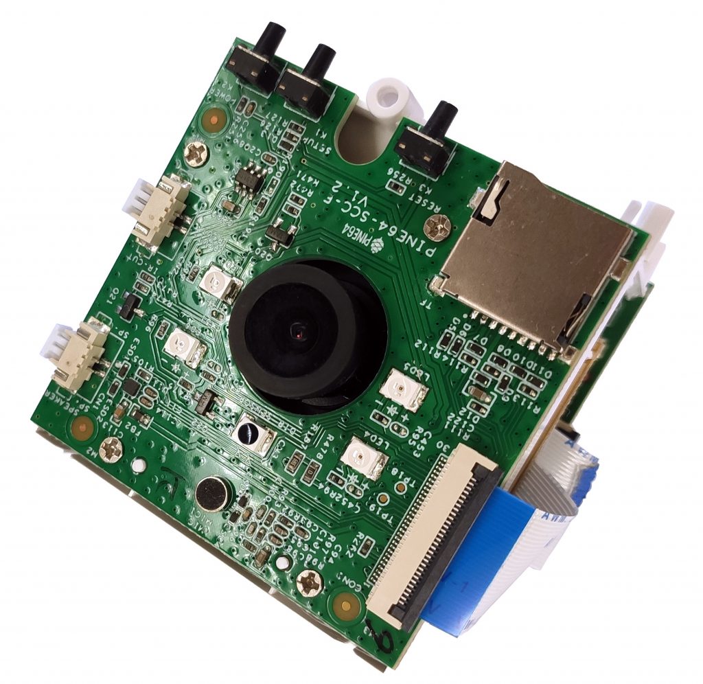
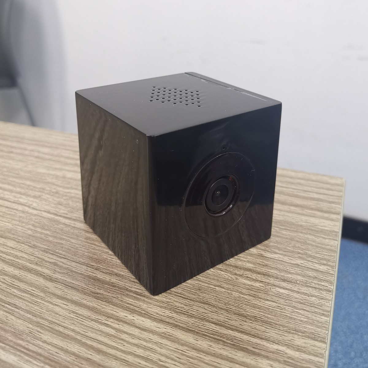
The PineCube is a small, low-powered, open source IP camera. Whether you’re a parent looking for a FOSS baby-camera, a privacy oriented shop keeper, home owner looking for a security camera, or perhaps a tinkerer needing a camera for your drone – the CUBE can be the device for you. It features an 5MPx Omnivision sensor and IR LEDs for night vision, as well as Power Over Ethernet, as well as a microphone.
Specifications
- Dimensions: 55mm x 51mm x 51.5mm
- Weight: 55g
- Storage:
- MicroSD slot, bootable
- 128Mb SPI Nor Flash, bootable
- Cameras: OV5640, 5Mpx
- CPU: Allwinner(Sochip) ARM Cortex-A7 MPCore, 800MHz
- RAM: 128MB DDR3
- I/O:
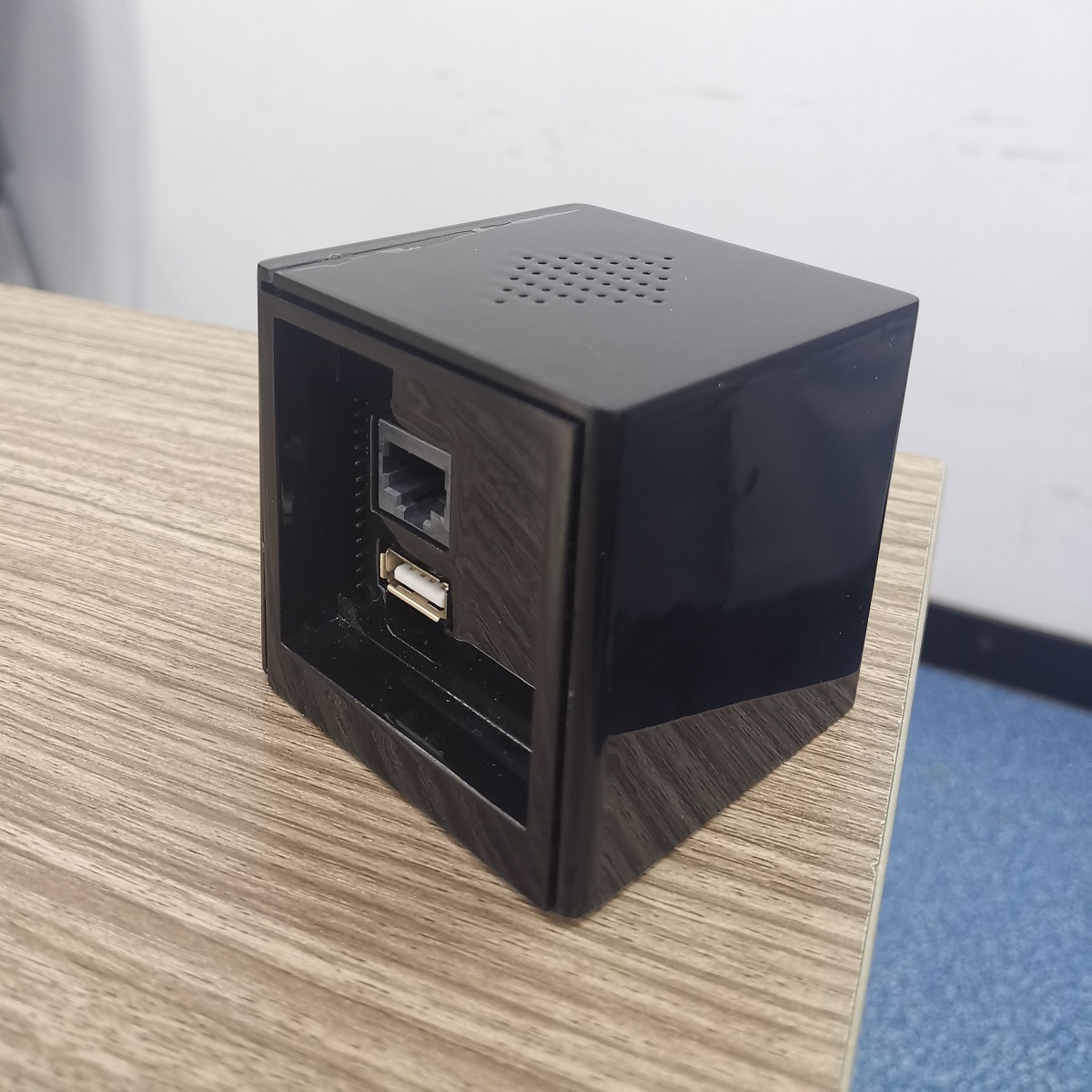
- 10/100Mbps Ethernet with passive PoE (4-18V!)
- USB 2.0 A host
- 26 pins GPIO port
- 2x 3.3V Ouptut
- 2x 5V Output
- 1x I2C
- 2x UART (3.3V)
- 2x PWM
- 1x SPI
- 1x eMMC/SDIO/SD (8-bit)
- 6x Interrupts
- Note: Interfaces are multiplexed, so they can't be all used at same time
- Internal microphone
- Network:
- WiFi
- Screen: optional 4.5" RGB LCD screen ( RB043H40T03A-IPS or DFC-XS4300240 V01 )
- Misc. features:
- Volume and home buttons
- Speakers and Microphone
- IR LEDs for night vision
- Passive infrared sensor
- Power DC in:
- 5V 1A from MicroUSB Port or GPIO port
- 4V-18V from Ethernet passive PoE
- Battery: optional 950-1600mAh model: 903048 Lithium Polymer Ion Battery Pack, can be purchase at Amazon.com
Board information, schematics and certifications
PineCube mainboard schematic:
PineCube faceboard schematic:
PineCube certifications:
Datasheets for components and peripherals
Allwinner (Sochip) S3 SoC information:
X-Powers AXP209 PMU (Power Management Unit) information:
CMOS camera module information:
LCD touch screen panel information:
Lithium battery information:
WiFi/BT module information:
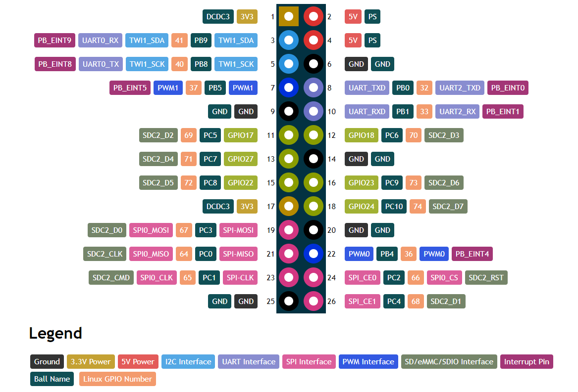
GPIO Header Pinout:
Note: Pin1 is marked on the board by a white dot on the PCB. See the PDF and HTML for details.
Case information
- Quick and dirty STL conversion (beta) by doodlebro. Prints and fits at 0.25mm layer height.
- New model with removable front cover and mouting plate with hole for strong magnet and adjustable rotation angle. See README for more details. Available FreeCAD source models, STL, G-code and 3mf data. Also available at printables.com
Operating Systems
Mainlining Efforts
Please note:
- this list is most likely not complete
- no review of functionality is done here, it only serves as a collection of efforts
| Linux kernel | ||
|---|---|---|
| Type | Link | Available in version |
| Devicetree Entry Pinecube | https://lkml.org/lkml/2020/9/22/1241 | 5.10 |
| Correction for AXP209 driver | https://lkml.org/lkml/2020/9/22/1243 | 5.9 |
| Additional Fixes for AXP209 driver | https://lore.kernel.org/lkml/20201031182137.1879521-8-contact@paulk.fr/ | 5.12 |
| Device Tree Fixes | https://lore.kernel.org/lkml/20201003234842.1121077-1-icenowy@aosc.io/ | 5.10 |
| Audio Device and IR LED Fix | https://github.com/danielfullmer/pinecube-nixos/blob/master/kernel/Pine64-PineCube-support.patch | TBD |
| U-boot | ||
| Type | Link | Available in version |
| PineCube Board Support | https://patchwork.ozlabs.org/project/uboot/list/?series=210044 | v2021.04 |
| Buildroot | ||
| Type | Link | Available in version |
| PineCube Board Support | https://patchwork.ozlabs.org/project/buildroot/list/?series=314653 | |
NixOS
Buildroot
Elimo Engineering integrated support for the PineCube into Buildroot.
This has not been merged into upstream Buildroot yet, but you can find the repository on Elimo's GitHub account and build instructions in the board support directory readme. The most important thing that this provides is support for the S3's DDR3 in u-boot. Unfortunately mainline u-boot does not have that yet, but the u-boot patches from Daniel Fullmer's NixOS repo were easy enough to use on buildroot. This should get you a functional system that boots to a console on UART0. It's pretty fast too, getting there in 1.5 seconds from u-boot to login prompt.
Armbian
The Ubuntu Groovy release is an experimental, automatically generated release and it appears to support additional hardware from the other Armbian releases.
Armbian Build Image with motion [microSD Boot] [20201222]
- Armbian Ubuntu Focal build for the Pinecube with the motion (detection) package preinstalled.
- There are 2 ways to interact with the OS:
- Scan for the the device IP (with hostname pinecube)
- Use the PINE64 USB SERIAL CONSOLE/PROGRAMMER to login to the serial console, then check for assigned IP
- DD image (for 8GB microSD card and above)
- Direct download from pine64.org
- MD5 (XZip file): 61e5a6d3ab0f74ce8367c97b7f8cbb7b
- File Size: 328MGB
- Direct download from pine64.org
GitHub gist for the user patch which pre-installs and configures the motion (detection) package.
Official Armbian builds for PineCube are available for download, once again thanks to the work of Icenowy Zheng. Although not officially supported it enables the usage of Debian and Ubuntu.
A serial console can be established with 1152008N1 (no hardware flow control). Login credentials are as usual in Armbian (login: root, password: 1234).
Motion daemon can be enabled using systemctl (With root) systemctl enable motion. Set the video settings in /etc/motion/motion.conf to 640x480 15fps YU12. Then just reboot. Note that motion currently takes considerable resources on the pinecube, so you'll want to stop it when doing things like apt upgrade and apt update with systemctl stop motion and then systemctl start motion
Serial connection using screen and the Woodpecker USB serial device
First set the Woodpecker's S1 jumper to 3V3. Then connect the Woodpecker USB serial device to the PineCube. Pin 1 on the PineCube has a small white dot on the PCB - this should be directly next to the micro-USB power connection. Attach the GND pin on the Woodpecker to pin 6 (GND) on the PineCube, TXD from the Woodpecker to pin 10 (UART_RXD) on the PineCube, and RXD from the Woodpecker to pin 8 (UART_TXD) on the PineCube.
On the host system which has the Woodpecker USB serial device attached, it is possible to run screen and to communicate directly with the PineCube:
screen /dev/ttyUSB0 115200
Serial connection using screen and Arduino Uno
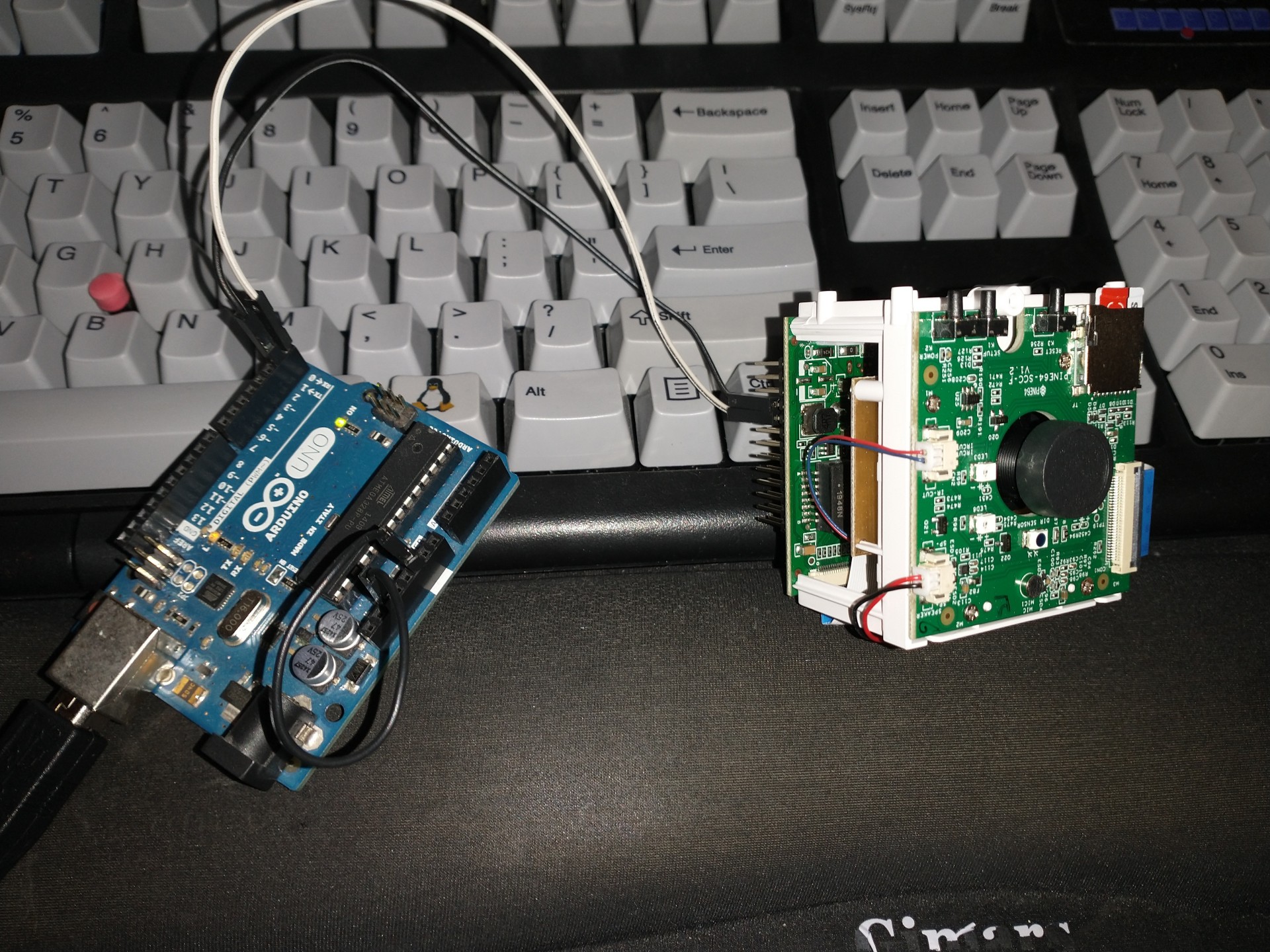
You can use the Arduino Uno or other Arduino boards as a USB serial device.
First you must either remove the microcontroller from it's socket, or if your Arduino board does not allow this, then you can use wires to jump RESET (RST) and GND to isolate the SOC.
After this you can either use the Arduino IDE and it's Serial monitor after selecting your /dev/ttyACMx Arduino device, or screen:
screen /dev/ttyACM0 115200
Serial connection using pinephone/pinebook pro serial debugging cable
You can use the serial console USB cable for pinephone and pinebook pro at the store. With a female terminal block wire using breadboard wire into the GPIO block at the following locations in a "null modem" configuration with transmit and receive crossed between your computer and the pinecube:
S - Ground (to pin 9)
R - Transmit (to pin 8)
T - Receive (to pin 10)
From Linux you can access the console of the pinecube using the screen command:
screen /dev/ttyUSB0 115200
Basic bandwidth tests with iperf3
Install armbian-config:
apt install armbian-config
Enable iperf3 through the menu in armbian-config:
armbian-config
On a test computer on the same network segment run iperf3 as a client:
iperf3 -c pinecube -t 60
The same test computer, run iperf3 in the reverse direction:
iperf3 -c pinecube -t 60 -R
PineCube as a WiFi AP
If the PineCube will have a wired ethernet connection to the main network it is possible to use it as a WiFi access point, possibly extending your existing network to further outside. Here are some steps you can take to do this starting from an Armbian system as a starting point. Note that you may need to upgrade your kernel to 5.13.x for this to work well.
- Install bridge-utils package using apt-get
- Add the following to your /etc/network/interfaces to set up both the eth0 ethernet interface and the br0 bridge interface (change br0 to manual if static IP is preferred)
/etc/network/interfaces:
auto eth0
iface eth0 inet manual
       pre-up /sbin/ifconfig $IFACE up
       pre-down /sbin/ifconfig $IFACE down
auto br0
iface br0 inet dhcp
       bridge_ports eth0
       bridge_stp on
- Edit the /etc/default/hostapd uncommenting the line with 'DAEMON_CONF="/etc/hostapd.conf"'
- Edit the /etc/hostapd.conf to set the SSID, password and channel for your AP.
- Run
sudo systemctl enable hostapd.serviceto enable the hostapd service on startup - Reboot your cube with the ethernet cable connected
PineCube as a webcam
The PineCube can be powered by the host and communicate as a peripheral. First, you'll need to a dual USB-A (male) cable to plug it into your computer. Note that the Micro-USB port can be used only for power because the data lines are not connected.
USB as an Ethernet gadget
Goal: To achieve fast (low latency) wired network connection via USB-A port of PineCube. PineCube will be shown as a network device when connected to a computer via USB-A port. You can set up the computer to be in the same network as PineCube and connect to PineCube via SSH and/or Stream Videos from it.
1. Additional patch to PineCube device tree disable ehci0 and ohci0, enabling usb_otg device instead and setting dr_mode to otg. If otg is not working for you, try setting dr_mode to peripheral. On Armbian there is no need for disabling ehci0 and ohci0. Device tree can be edited via armbian-config tool on Armbian OS. (armbian-config -> System -> DTC)
- sample DTC on Armbian:
               -----

               usb@1c19000 {
                       compatible = "allwinner,sun8i-h3-musb";
                       reg = <0x1c19000 0x400>;
                       clocks = <0x03 0x1d>;
                       resets = <0x03 0x11>;
                       interrupts = <0x00 0x47 0x04>;
                       interrupt-names = "mc";
                       phys = <0x0e 0x00>;
                       phy-names = "usb";
                       extcon = <0x0e 0x00>;
                       status = "okay";
                       dr_mode = "otg";
                       phandle = <0x2c>;
               };

               -----
2. Load necessary kernel modules. You can skip this step if you use Armbian OS because necessary modules are already loaded by default (Detailed instructions for sunxi and ethernet gadget: https://linux-sunxi.org/USB_Gadget/Ethernet)
modprobe sunxi
modprobe configfs
modprobe libcomposite
modprobe u_ether
modprobe usb_f_rndis
3. Add sunxi and g_ether to /etc/modules to get them to load on startup
/etc/modules:
sunxi
g_ether
4. Configure the g_ether device to start with a stable MAC address
/etc/modprobe.d/g_ether.conf:
options g_ether host_addr=f6:11:fd:ed:ec:6e
5. Set a static IP address for usb0 on startup with network manager
/etc/network/interfaces:
  auto usb0
  iface usb0 inet static
      address 192.168.10.2
      netmask 255.255.255.0
6. Boot the PineCube plugging it into a computer 7. Configure the USB ethernet device on the computer to be in the same subnet as the pinecube
- Sample setting:
network setting: Manual
address: 192.168.10.5
netmask: 255.255.255.0
gateway: 192.168.10.2
8. Done. You can use above methods to stream video through this USB ethernet connection. Bandwith and response time is much faster compared to usual network methods
USB as a Webcam (UVC) gadget (Work In Progress)
Goal: Make PineCube behave almost as same as like normal Webcam. When you connect PineCube to a computer it will be shown as a webcam device. No need for an additional set up you can use it straight after plugging the PineCube to a computer. USB-A port is for data transfer between PineCube and computer/phone. Micro-USB port is for power.
Action Plan (by Newton688):
-Attempt to load the uvc_gadget (usb_f_uvc) or g_webcam
-Look at this project to see if it can bridge UVC gadget output with the v4l from the OV5650 camera sensor
 https://github.com/wlhe/uvc-gadget
Progress report so far (by Disctanger):
Configfs method is going to be used to control OTG port.
1. Additional patch to PineCube device tree disable ehci0 and ohci0, enabling usb_otg device instead and setting dr_mode to otg. If otg is not working for you, try setting dr_mode to peripheral. On Armbian there is no need for disabling ehci0 and ohci0. Device tree can be edited via armbian-config tool on Armbian OS. (armbian-config -> System -> DTC)
- sample DTC on Armbian:
               -----

               usb@1c19000 {
                       compatible = "allwinner,sun8i-h3-musb";
                       reg = <0x1c19000 0x400>;
                       clocks = <0x03 0x1d>;
                       resets = <0x03 0x11>;
                       interrupts = <0x00 0x47 0x04>;
                       interrupt-names = "mc";
                       phys = <0x0e 0x00>;
                       phy-names = "usb";
                       extcon = <0x0e 0x00>;
                       status = "okay";
                       dr_mode = "otg";
                       phandle = <0x2c>;
               };

               -----
2. Load necessary kernel modules.
modprobe sunxi
modprobe configfs
modprobe libcomposite
3. Set up camera so that it would capture images in YUYV format (Currently only supported format in UVC gadget). You can adjust resolutions but have to adjust Configfs set up step as well.
media-ctl --set-v4l2 '"ov5640 1-003c":0[fmt:YUYV8_2X8/640x480@1/30]'
4. Clone UVC gadget repo for raspberry pi to your PineCube
git clone https://github.com/peterbay/uvc-gadget.git
cd uvc_gadget
5. Comment out 1182~1185 lines of `uvc-gadget.c` file:
//    if (!uvc_shutdown_requested && ((uvc_dev.dqbuf_count + 1) >= uvc_dev.qbuf_count)) {
//        return;
//    }
6. Build the source code inside PineCube using make command. It takes only few seconds to build the code.
make
gcc -W -Wall -g   -c -o uvc-gadget.o uvc-gadget.c
gcc -g -o uvc-gadget uvc-gadget.o
7. Set up configfs (multi-gadget):
You can have the following script as a bash script as well.
 GADGET_PATH=/sys/kernel/config/usb_gadget/pinecube

 mkdir $GADGET_PATH


 echo 0x1d6b > $GADGET_PATH/idVendor
 echo 0x0104 > $GADGET_PATH/idProduct
 echo 0x0100 > $GADGET_PATH/bcdDevice
 echo 0x0200 > $GADGET_PATH/bcdUSB

 echo 0xEF > $GADGET_PATH/bDeviceClass
 echo 0x02 > $GADGET_PATH/bDeviceSubClass
 echo 0x01 > $GADGET_PATH/bDeviceProtocol

 mkdir $GADGET_PATH/strings/0x409
 echo 100000000d2386db > $GADGET_PATH/strings/0x409/serialnumber
 echo "Pine64" > $GADGET_PATH/strings/0x409/manufacturer
 echo "PineCube Webcam" > $GADGET_PATH/strings/0x409/product
 mkdir $GADGET_PATH/configs/c.1
 mkdir $GADGET_PATH/configs/c.1/strings/0x409
 echo 500 > $GADGET_PATH/configs/c.1/MaxPower
 echo "UVC" > $GADGET_PATH/configs/c.1/strings/0x409/configuration

 mkdir $GADGET_PATH/functions/uvc.usb0
 mkdir $GADGET_PATH/functions/acm.usb0
 echo 512 > $GADGET_PATH/functions/uvc.usb0/streaming_maxpacket
 # cat <<EOF $GADGET_PATH/functions/uvc.usb0/control/processing/default/bmControls
 # 0
 # 0
 # EOF

 mkdir -p $GADGET_PATH/functions/uvc.usb0/control/header/h
 ln -s $GADGET_PATH/functions/uvc.usb0/control/header/h $GADGET_PATH/functions/uvc.usb0/control/class/fs/h
 # ln -s $GADGET_PATH/functions/uvc.usb0/control/header/h $GADGET_PATH/functions/uvc.usb0/control/class/hs/h
 # ln -s $GADGET_PATH/functions/uvc.usb0/control/header/h $GADGET_PATH/functions/uvc.usb0/control/class/ss/h

 config_frame () {
     FORMAT=$1
     NAME=$2
   WIDTH=$3
   HEIGHT=$4

     framedir=$GADGET_PATH/functions/uvc.usb0/streaming/$FORMAT/$NAME/${HEIGHT}p

     mkdir -p $framedir

     echo $WIDTH > $framedir/wWidth
     echo $HEIGHT > $framedir/wHeight
     echo 333333 > $framedir/dwDefaultFrameInterval
     echo $(($WIDTH * $HEIGHT * 80)) > $framedir/dwMinBitRate
     echo $(($WIDTH * $HEIGHT * 160)) > $framedir/dwMaxBitRate
     echo $(($WIDTH * $HEIGHT * 2)) > $framedir/dwMaxVideoFrameBufferSize
     cat <<EOF > $framedir/dwFrameInterval
 333333
 400000
 666666
 EOF

 }

 config_frame mjpeg m 640 360
 config_frame mjpeg m 640 480
 config_frame mjpeg m 800 600
 config_frame mjpeg m 1024 768
 config_frame mjpeg m 1280 720
 config_frame mjpeg m 1280 960
 config_frame mjpeg m 1440 1080
 config_frame mjpeg m 1536 864
 config_frame mjpeg m 1600 900
 config_frame mjpeg m 1600 1200
 config_frame mjpeg m 1920 1080

 SMALL_WIDTH=480p

 mkdir -p $GADGET_PATH/functions/uvc.usb0/streaming/uncompressed/u/$SMALL_WIDTH

 echo 640 > $GADGET_PATH/functions/uvc.usb0/streaming/uncompressed/u/$SMALL_WIDTH/wWidth
 echo 480 > $GADGET_PATH/functions/uvc.usb0/streaming/uncompressed/u/$SMALL_WIDTH/wHeight
 echo 333333 > $GADGET_PATH/functions/uvc.usb0/streaming/uncompressed/u/$SMALL_WIDTH/dwDefaultFrameInterval
 echo $((640 * 480 * 80)) > $GADGET_PATH/functions/uvc.usb0/streaming/uncompressed/u/$SMALL_WIDTH/dwMinBitRate
 echo $((640 * 480 * 160)) > $GADGET_PATH/functions/uvc.usb0/streaming/uncompressed/u/$SMALL_WIDTH/dwMaxBitRate
 echo $((640 * 480 * 2)) > $GADGET_PATH/functions/uvc.usb0/streaming/uncompressed/u/$SMALL_WIDTH/dwMaxVideoFrameBufferSize
 cat <<EOF > $GADGET_PATH/functions/uvc.usb0/streaming/uncompressed/u/$SMALL_WIDTH/dwFrameInterval
 333333
 400000
 666666
 EOF

 mkdir $GADGET_PATH/functions/uvc.usb0/streaming/header/h
 cd $GADGET_PATH/functions/uvc.usb0/streaming/header/h
 # ln -s ../../mjpeg/m
 ln -s ../../uncompressed/u
 cd ../../class/fs
 ln -s ../../header/h
 cd ../../class/hs
 ln -s ../../header/h
 cd ../../../../..

 ln -s $GADGET_PATH/functions/uvc.usb0 $GADGET_PATH/configs/c.1/uvc.usb0
 ln -s $GADGET_PATH/functions/acm.usb0 $GADGET_PATH/configs/c.1/acm.usb0
 udevadm settle -t 5 || :
 ls /sys/class/udc > $GADGET_PATH/UDC
If above script goes without issues you should be able to see one more additional `/dev/video*` device.
8. run uvc-gadget
UVC Gadget software links camera of PineCube and UVC gadget (OTG port).
"-v" is for video input device - PineCube Camera, "-u" is for output video device UVC device or OTG port, -x shows FPS.
./uvc-gadget -u /dev/video1 -v /dev/video0 -x
9. Plug the PineCube to your laptop or pc and check if you can see PineCube Webcam.
Known issues:
- Low Frame rate(3FPS~5FPS). That is because:
- At the time of writing this section, `streaming_maxpacket` value cannot be set to max value (2048 bytes.) It can be set only to 512 bytes. If `streaming_maxpacket` is set to max (2048) value, UDC cannot be turned on with `Invalid Value` error.
- YUYV (uncompressed) file format is being used to stream the images. Uncompressed images take a lot of USB bandwidth compared to compressed. We can stream more frames, if MJPEG or even H254 (compressed images) would be used. I will be investigating further on how to stream more frames through USB port.
PineCube as a recorder for loud noises
If you have a kernel that has the sound support (see the Sound Control section) then you can use it to make recordings when there is a noise above a certain threshold. The following script is a very simple example that uses the alsa-utils and the sox command to do this. You can use the noise-stats.txt file and some noise testing to figure out a good threshold for your camera.
#!/bin/bash

# Directory where the sound recordings should go
NOISE_FILE_DIR="/root/noises"

# Threshold to use with the mean delta to decide to preserve the recording
MEAN_DELTA_THRESHOLD="0.002"

# Sample length (in seconds)
SAMPLE_LENGTH="10"

while :
do
     stats=$(arecord -d "$SAMPLE_LENGTH" -f S16_LE > /tmp/sample.wav 2>/dev/null && sox -t .wav /tmp/sample.wav -n stat 2>&1 | grep 'Mean    delta:' | cut -d: -f2 | sed 's/^[ ]*//')
     ts=$(date +%s)
     if (( $(echo "$stats > $MEAN_DELTA_THRESHOLD" | bc -l) )); then
          mv /tmp/sample.wav "$NOISE_FILE_DIR/noise-$ts.wav" # TODO convert to mp3
     fi
     rm -f /tmp/sample.wav
     echo "$ts $stats" >> noise-stats.txt
done
Debugging camera issues with the gstreamer pipeline
If the camera does not appear to work, it is possible to change the v4l2src to videotestsrc and the gstreamer pipeline will produce a synthetic test image without using the camera hardware.
If the camera is only sensor noise lines over a black or white image, the camera may be in a broken state. When in that state, the following kernel messages were observed:
[ 1703.577304] alloc_contig_range: [46100, 464f5) PFNs busy
[ 1703.578570] alloc_contig_range: [46200, 465f5) PFNs busy
[ 1703.596924] alloc_contig_range: [46300, 466f5) PFNs busy
[ 1703.598060] alloc_contig_range: [46400, 467f5) PFNs busy
[ 1703.600480] alloc_contig_range: [46400, 468f5) PFNs busy
[ 1703.601654] alloc_contig_range: [46600, 469f5) PFNs busy
[ 1703.619165] alloc_contig_range: [46100, 464f5) PFNs busy
[ 1703.619528] alloc_contig_range: [46200, 465f5) PFNs busy
[ 1703.619857] alloc_contig_range: [46300, 466f5) PFNs busy
[ 1703.641156] alloc_contig_range: [46100, 464f5) PFNs busy
Camera Adjustments
Focus
The focus of the lens can be manually adjusted through rotation. Note that initially, the lens could be tight.
Low light mode
To get imagery in low-light conditions you can turn on the infrared LED's to light up the dark area and also enable the IR cut filter using the commands below. Note that these were performed on Armbian using the instructions from here [1].
# Run these as root

# Turn on the IR LED lights (note that you can see a faint red glow from them when it's low light)
# Turn them off with echo 1 instead (this may be inverted depending on the version of the kernel you have)
# echo 0 > /sys/class/leds/pine64\:ir\:led1/brightness
# echo 0 > /sys/class/leds/pine64\:ir\:led2/brightness

# Export gpio, set direction
# echo 45 > /sys/class/gpio/export
# echo out > /sys/class/gpio/gpio45/direction

# Enable IR cut filter (note that you can hear the switching noise)
# Disable with echo 0 instead
# echo 1 > /sys/class/gpio/gpio45/value
Camera controls
It is possible to adjust the camera using certain internal camera controls, such as contrast, brightness, saturation and more. These controls can be accessed using the v4l2-ctl tool that is part of the v4l-utils package.
# List the current values of the controls
v4l2-ctl -d /dev/v4l-subdev* --list-ctrls

User Controls

                       contrast 0x00980901 (int)    : min=0 max=255 step=1 default=0 value=0 flags=slider
                     saturation 0x00980902 (int)    : min=0 max=255 step=1 default=64 value=64 flags=slider
                            hue 0x00980903 (int)    : min=0 max=359 step=1 default=0 value=0 flags=slider
        white_balance_automatic 0x0098090c (bool)   : default=1 value=1 flags=update
                    red_balance 0x0098090e (int)    : min=0 max=4095 step=1 default=0 value=0 flags=inactive, slider
                   blue_balance 0x0098090f (int)    : min=0 max=4095 step=1 default=0 value=0 flags=inactive, slider
                       exposure 0x00980911 (int)    : min=0 max=65535 step=1 default=0 value=4 flags=inactive, volatile
                 gain_automatic 0x00980912 (bool)   : default=1 value=1 flags=update
                           gain 0x00980913 (int)    : min=0 max=1023 step=1 default=0 value=20 flags=inactive, volatile
                horizontal_flip 0x00980914 (bool)   : default=0 value=0
                  vertical_flip 0x00980915 (bool)   : default=0 value=0
           power_line_frequency 0x00980918 (menu)   : min=0 max=3 default=1 value=1

Camera Controls

                  auto_exposure 0x009a0901 (menu)   : min=0 max=1 default=0 value=0 flags=update

Image Processing Controls

                     pixel_rate 0x009f0902 (int64)  : min=0 max=2147483647 step=1 default=61430400 value=21001200 flags=read-only
                   test_pattern 0x009f0903 (menu)   : min=0 max=4 default=0 value=0

# Set the contrast controls to the maximum value
v4l2-ctl -d /dev/v4l-subdev* --set-ctrl contrast=255
You can see which flags can be changed and which ones cannot by looking at the flags. The inactive flag indicates that it is currently disabled. Some of these flags are disabled when other flags are turned on. For example, the gain flag above is inactive because gain_automatic is enabled with a value of "1." Note that at the current time the auto_exposure flag is inverted, so a value of "0" means on, while "1" means off. Maybe the auto_exposure flag will get changed someday. You'll need to turn off auto_exposure (value=1) if you want to manually set the exposure flag.
Sound Controls
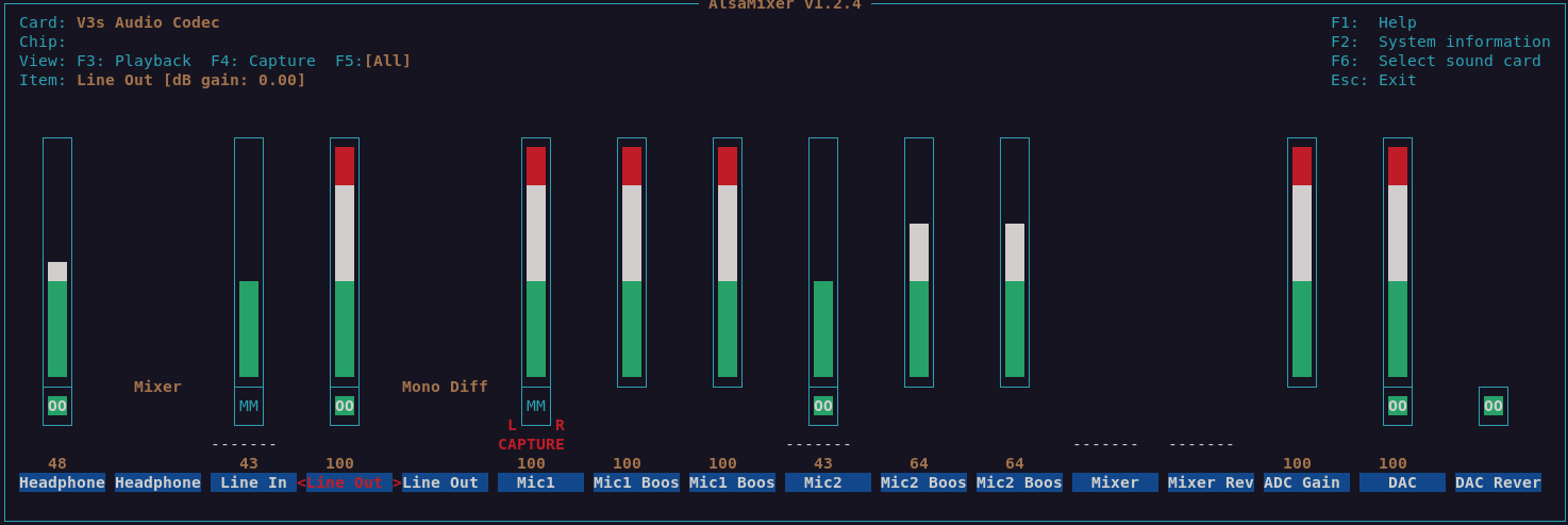
Note that sound is only currently available with special patches on top of a 5.13.13 or higher kernel with Armbian or NixOS. Once you have a kernel that supports sound you can install alsa-utils to get the alsamixer tool. The following mixer settings have been found to work with both playback and record. Note that you'll need to press F5 to get the capture controls and space bar to turn on/off capture for a device. The speaker dangles on a wire from the device. The microphone is located about 1cm below the lens on the front facing circuit board.
SDK
Stock Linux
- Direct Download from pine64.org
- MD5 (7zip file): efac108dc98efa0a1f5e77660ba375f8
- File Size: 3.50GB
How to compile
You can either setup a machine for the build environment, or use a Vagrant virtual machine provided by Elimo Engineering
On a dedicated machine
Recommended system requirements:
- OS: (L)Ubuntu 16.04
- CPU: 64-bit based
- Memory: 8 GB or higher
- Disk: 15 GB free hard disk space
Install required packages
sudo apt-get install p7zip-full git make u-boot-tools libxml2-utils bison build-essential gcc-arm-linux-gnueabi g++-arm-linux-gnueabi zlib1g-dev gcc-multilib g++-multilib libc6-dev-i386 lib32z1-dev
Install older Make 3.82 and Java JDK 6
pushd /tmp
wget https://ftp.gnu.org/gnu/make/make-3.82.tar.gz
tar xfv make-3.82.tar.gz
cd make-3.82
./configure
make
sudo apt purge -y make
sudo ./make install
cd ..
# Please, download jdk-6u45-linux-x64.bin from https://www.oracle.com/java/technologies/javase-java-archive-javase6-downloads.html (requires free login)
chmod +x jdk-6u45-linux-x64.bin
./jdk-6u45-linux-x64.bin
sudo mkdir /opt/java/
sudo mv jdk1.6.0_45/ /opt/java/
sudo update-alternatives --install /usr/bin/javac javac /opt/java/jdk1.6.0_45/bin/javac 1
sudo update-alternatives --install /usr/bin/java java /opt/java/jdk1.6.0_45/bin/java 1
sudo update-alternatives --install /usr/bin/javaws javaws /opt/java/jdk1.6.0_45/bin/javaws 1
sudo update-alternatives --config javac
sudo update-alternatives --config java
sudo update-alternatives --config javaws
popd
PineCubes SPI Flash support patch
From 9316112c37ee86645fd691c6d3352183b95177d8 Mon Sep 17 00:00:00 2001
From: Marek Kraus <gamelaster@outlook.com>
Date: Fri, 8 Jul 2022 21:01:47 +0200
Subject: [PATCH] Add support for xt25f128 SPI Flash

---
 drivers/mtd/devices/m25p80.c | 1 +
 1 file changed, 1 insertion(+)

diff --git a/drivers/mtd/devices/m25p80.c b/drivers/mtd/devices/m25p80.c
index 31e5795..0f46a4c 100755
--- a/drivers/mtd/devices/m25p80.c
+++ b/drivers/mtd/devices/m25p80.c
@@ -803,6 +803,7 @@ static const struct spi_device_id m25p_ids[] = {
 	{ "w25x64", INFO(0xef3017, 0, 64 * 1024, 128, SECT_4K) },
 	{ "w25q64", INFO(0xef4017, 0, 64 * 1024, 128, SECT_4K) },
 	{ "W25q128", INFO(0xef4018, 0, 64 * 1024, 256, 0) },
+	{ "xt25f128", INFO(0x0b4018, 0, 64 * 1024, 256, SECT_4K) },


 	/* Catalyst / On Semiconductor -- non-JEDEC */
--
2.7.4
Unpack SDK and then compile and pack the image
7z x 'PineCube Stock BSP-SDK ver1.0.7z'
mv 'PineCube Stock BSP-SDK ver1.0' pinecube-sdk
cd pinecube-sdk/camdroid
# apply SPI Flash patch above or edit m25p80.c file
source build/envsetup.sh
lunch # select [1] here
mklichee
extract-bsp
make -j3
pack
Using Vagrant
You can avoid setting up your machine and just use Vagrant to spin up a development environment in a VM.
Just clone the Elimo Engineering repo and follow the instructions in the readme file
After spinning up the VM, you just need to run the build:
cd pinecube-sdk/camdroid
# apply SPI Flash patch above or edit m25p80.c file
source build/envsetup.sh
lunch # select [1] here
mklichee
extract-bsp
make -j3
pack
Flashing the image
Manual on how to flash Allwinners BSP images
Community Projects
Share your project with a PineCube here!
| Project Homepage | Project Source | PineCube Implementations | |
|---|---|---|---|
| openWRT | JuanEst | juansef packaes | Pine64 Forum thread |
