Wifi Remote I2c
Jump to navigation
Jump to search

Quick Start Guide
Hardware Setup

- Make sure that the driver for USB/UART Programming/Console Adapter (PMPROG01) is properly install and the PC is detected it as Comm Port.
- The USB/UART Bridge is base on Silicon Lab CP2012 chipset.
- USB/UART Programming/Console Adapter (PMPROG01) driver can be Download here
- Connect the USB/UART Programming/Console Adapter (PMPROG01) to the Wifi Remote I2c Device.
- You can power-up the WiFI Remote I2c module through the USB Bus for configuration and programming.
 Place the jumper J2 on USB/UART Programming/Console Adapter (PMPROG01) to 5V output selection.
Setting Configuration


- For windows system, you can use terminal emulator program Termite to configure the device.
- Termite can be downloaded at CompuPhase Website
- Make sure the 'Port' setting is refer to the USB/UART Programming/Console Adapter (PMPROG01)'s Virtual Comm Port.
- Follow the setting according to the setup screen capture. (57600Baud 8-N-1)
- Once Termite configuration is done, press 'OK' to save the setting.
- On the Wifi Remote I2c Device, Press the configuration button to allow the device to go into configuration mode.
 Press Config Mode button to go into configuration mode
- Type 'help' to show the command available for configuration.
- Type 'show' to list out current configuration.
- We will use PineA64 as our Wifi Remote I2c module's server.
- To Set the PineA64's IP address in to the device, enter (we will be using IP address 192.168.0.230 as example)
server 192.168.0.230
- To configure the Wifi AP SSID and Password, (eg SSID=TestingWifi and Password=12345 )
wifi TestingWifi 12345
- The SSID and password are case sensitive. Please make sure it is input correctly.
- Once configuration is done, type 'exit' to exit configuration mode and allow the device to reboot.
- Please make sure your network is has DHCP server. The WiFi Remote i2c module will be running on DHCP mode and will requesting a IP address from your network's DHCP server.
- After reboot, the Red LED indicator will start to blink in fast blinking mode.
- Once the WiFi Remote I2c module connected to the WiFi Access Point, the LED indicator will go into slow blinking mode.
- The hardware configuration is done.
- The next step will be configure the PineWifiServer into your PineA64 board.
Setup the PineWifiServer
- Download the PineWifiServer from the Download Section
- Copy PineWifiServer xxxxxxxx.gz into your PineA64 with linux on it. (where xxxxxxxx is the version number)
- Unzip the file using gunzip.
- Add Execution flag on both of the file by
chmod +x PineWifiServer
- Start the PineWifiServer by
./PineWifiServer
- Once the server is started, you will notice that the LED indicator on the Wifi Remote I2c Hardware will change from slow blinking to always on.
- To login into the server, telnet into localhost port 10000
telnet localhost 10000

- To show current connect Wifi Remote I2c type 'list' in small capital letter.
- To see all available command, type 'help'.
- To exit the console, type 'exit'.
- Please take note that you are only allow one login simultaneously. The second telnet login will be rejected.
Running the WifiAppDemo
- Download the PineWifiServer from the Download Section
- Copy WifiAppDemo xxxxxxxx.gz into your same PineA64 board that currently running with PineWifiServer. (where xxxxxxxx is the version number)
- Unzip both of the file using gunzip.
- Add Execution flag on both of the file by
chmod +x WifiAppDemo
- before start running the demo application, please logout any telnet session to the PineWifiServer.
- The demo application will telnet into the PineWifiServer and start polling all the available Wifi Remote I2c device currently connected to the server.
- The demo application will also poll the I2c port of the hardware for the Ambient Light Sensor and the Temperature/Humidity Sensor if the sensor is connected to the Wifi Remote I2c module.
- To start the WifiAppDemo, type
./WifiAppDemo
- The Application will connect the PineWifiServer currently running in the localhost.

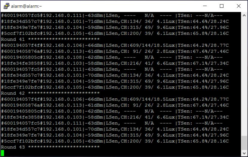
Example of screen shot with WifiAppDemo polling multiple Wifi Remote I2c with Ambient Light Sensor and Humidity/Temperature Sensor connected on it. The speed for each round of polling is 1 second per poll.
Firmware Upgrade
Hardware Setup
 Short Jumper S2 on the WiFI Remote I2c module (before power up the board) to allow the board to go in to firmware programming mode.
- Make sure that the driver for USB/UART Programming/Console Adapter (PMPROG01) is properly install and the PC is detected it as Comm Port.
- The USB/UART Bridge is base on Silicon Lab CP2012 chipset.
- USB/UART Programming/Console Adapter (PMPROG01) driver can be Download here
- Connect the USB/UART Programming/Console Adapter (PMPROG01) to the Wifi Remote I2c Device.
- You can power-up the WiFI Remote I2c module through the USB Bus for configuration and programming.
Place the jumper J2 on USB/UART Programming/Console Adapter (PMPROG01) to 5V output selection.
Software Setup
- Download the firmware from the download section and unzip the file.
- Download the windows Python base Flash Download Tools by Espressif from Espressif website.
- Setup the ESP Flash Download tools according to the screen short.

- Make sure that the firmware address is set correctly. Baud rate is set to 115200baud and Com Port is set according to the Virtual Com Port of your PC.
- Once the ESP Flash Download tool and hardware is setup properly, press the 'Start' button to start the firmware uploading process.
- After uploading is done, power off and on again the WiFi Remote I2c module to restart the system.
Technical Specification
- Dimension : 47.00mm x 34.00mm
- Input Voltage : 5V
- Max. Input Current: 200mA
- Operating Frequency: 2412MHz-2484MHz
- Output power of PA for 802.11b: 19.5dBm-21.5dBm
- Recieived Sensitivity at DSSS, 1Mbps: -98dBm
I/O Pin Out

Download
Program/Driver
- Termite a simple RS232 terminal
- Flash Download Tools v2.4 Under Tools Section
- Silicon Lab CP2102 Virtual COM Port Driver
- WifiAppDemo.gz
- PineWifiServer.gz
- PMWF01A Firmware
- PMWF01A Firmware Source
- PineWifiRemoteI2c Server Source.tar.gz