PINE A64-LTS

The PINE64-LTS is the long term supply version of the PINE A64 (+), PINE64's first single board computer, powered by Allwinner’s A64 quad-core ARM Cortex A53 64-Bit SoC. There are many operating systems available for the PINE A64-LTS created by the open source community and various partner projects. The PINE A64-LTS is guaranteed to be supplied until the year 2025 at the very least.
Software releases
The SOPINE operating system images are compatible with PINE A64-LTS. Under SOPINE Software Releases you will find a complete list of currently supported operating system images, which work with the PINE A64-LTS, as well as other related software.
Accessories and Step-by-Step Guides
Please see Accessories Step by Step Guides for a list of guides for Pine A64 accessories; there you can find instructions and guides about the following:
- Enclosures
- Bluetooth and WiFi module
- Real Time Clock (RTC) battery
- Real Time Clock (RTC) battery holder
- First and third party cases
- Featured 3D printed cases (and more)
SoC and Memory Specification


The PINE A64-LTS is based on the Allwinner A64/R18. The R18 and A64 are identical SoCs but the is R18 committed for a 10 years supply by the vendor.
CPU Architecture
- Quad-core ARM Cortex-A53 Processor@1152Mhz
- A power-efficient ARM v8 architecture
- 64 and 32bit execution states for scalable high performance
- Support NEON Advanced SIMD (Single Instruction Multiple Data) instruction for acceleration of media and signal processing function
- Support Large Physical Address Extensions(LPAE)
- VFPv4 Floating Point Unit
- 32KB L1 Instruction cache and 32KB L1 Data cache
- 512KB L2 cache
GPU Architecture
- ARM Mali400MP2 Dual-core GPU
- Support OpenGL ES 2.0 and OpenVG 1.1 standard
System Memory
- RAM Memory Variants: 2GB LPDDR3.
- Storage Memory: 128Mb SPI Flash and optional eMMC module from 16GB up to 128GB
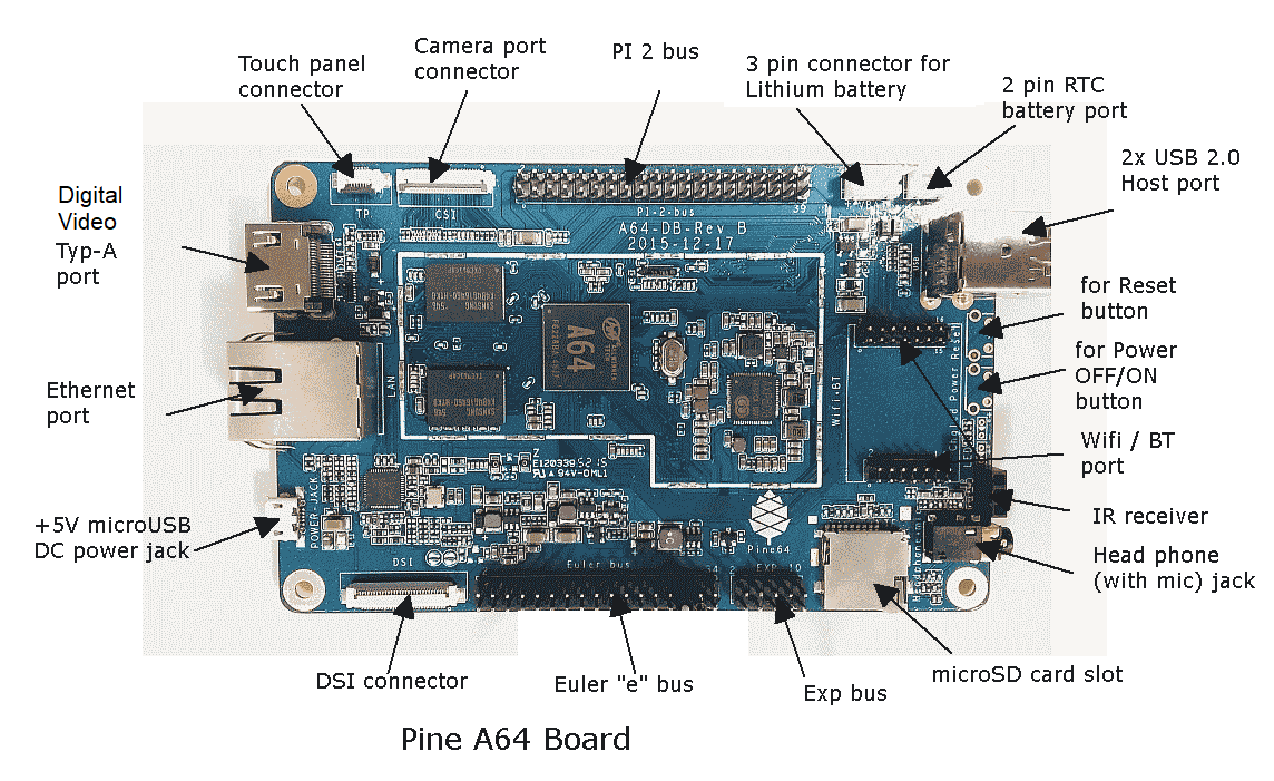
PINE A64-LTS Board Features


Video
- Digital Video (Type A - full)
Audio
- 3.5mm stereo earphone/microphone plug
Network
- 10/100/1000Mbps Ethernet(PINE A64+ version), 10/100Mbps Ethernet(PINE A64 version)
- WiFi 802.11 b/g/n with Bluetooth 4.0 (optional)
Storage
- microSD - bootable, support SDHC and SDXC, storage up to 256GB
- USB - 2 USB2.0 Host port
Expansion ports
- DSI - Display Serial Interface, four-lane MiPi, up to 1080p
- CSI - CMOS Camera Interface up to 5 megapixel
- TP - Touch Panel Port, SPI with interrupt
- RTC - Real Time Clock Battery Connector
- VBAT - Lithium Battery Connector with temperature sensor input
- Wifi/BT Module Header - SDIO 3.0 and UART
- 2x20 pins "Pi2" GPIO Header
- 2x17 pins "Euler" GPIO Header
- 2x5 pins "EXP" Console Header
Serial console UART

The "EXP" header, listed above, includes the TX, RX and GND pins for the serial console UART, also known as the debug UART, as visible in the picture in this section. The pin numbers are silkscreened on the top side of the A64-LTS PCB, making navigation easy.
This can be used to access the serial console of the boot loader, for example, which is often invaluable for debugging boot issues. To actually access the serial console, you can use these pins to connect, for example, a USB UART adapter that supports 3.3 V on the RX and TX lines, such as the "Woodpecker" USB UART adapter offered by the Pine Store.
Taking the "Woodpecker" USB UART adapter as an example, its pins should be connected to the pins of the "EXP" header as described in the table below, with the "5V" and "3V3" pins of the "Woodpecker" left unconnected. The voltage selection jumper found on the "Woodpecker" must be placed in the "3V3" position, as silkscreened on the top side of the "Woodpecker" PCB.
| "Woodpecker" pin | "EXP" header pin name | "EXP" header pin number |
|---|---|---|
| TxD | PB9_RX | 8 |
| RxD | PB8_TX | 7 |
| GND | GND (or GND1) | 9 (or 6) |
Board Data and Schematic
Model "A" Baseboard dimensions: 133 mm x 80 mm x 19 mm
Power inputs:
- DC barrel jack, 3.5 mm OD / 1.35 mm ID, 2 A at 5 V
- 3.7 V lithium-ion battery connector
- Euler connector
Schematics:
- PINE A64 Connector Layout @courtesy of norm24
- PINE A64 Connector List
- a PDF mapping the pins from the A64 chip itself, to the gold-fingers on the SO-DIMM edge, to the multiple connectors on the Baseboard and the Clusterboard, attached to this forum post
- PINE A64 Pi-2/Eular/Ext Bus/Wifi Bus Connector Pin Assignment (Updated 15/Feb/2016)
- Good documentation about PINE A64, A64+, and A64-LTS GPIO pins article and Archive.org link
Pine A64-LTS schematic:
Pine A64-LTS V2 schematic:
Datasheets for Components and Peripherals
Allwinner A64/R18 SoC information:
- Allwinner A64 SoC Brief Introduction
- Allwinner R18 SoC Brief Introduction
- Allwinner A64/R18 SoC Data Sheet V1.1 (Official Released Version)
- Allwinner A64/R18 SoC User Manual V1.0 (Official Release Version)
X-Powers AXP803 PMU (Power Management Unit) information:
LPDDR3 information:
eMMC information:
- PINE64 eMMC module schematic
- PINE64 USB adapter for eMMC module V2 schematic
- PINE64 USB adapter for eMMC module PCB in JPEG
- 16GB Foresee eMMC Datasheet
- 32GB/64GB/128GB SanDisk eMMC Datasheet
SPI NOR Flash information:
Related to the PINE A64-LTS:
- 5MPixel CMOS Camera module information:
- LCD Touch Screen Panel information:
- Lithium Battery information:
- Ethernet PHY information:
- Wifi/BT module information:
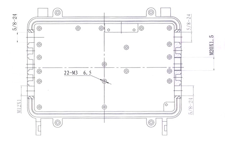
- Enclosure information:
- Connector information:
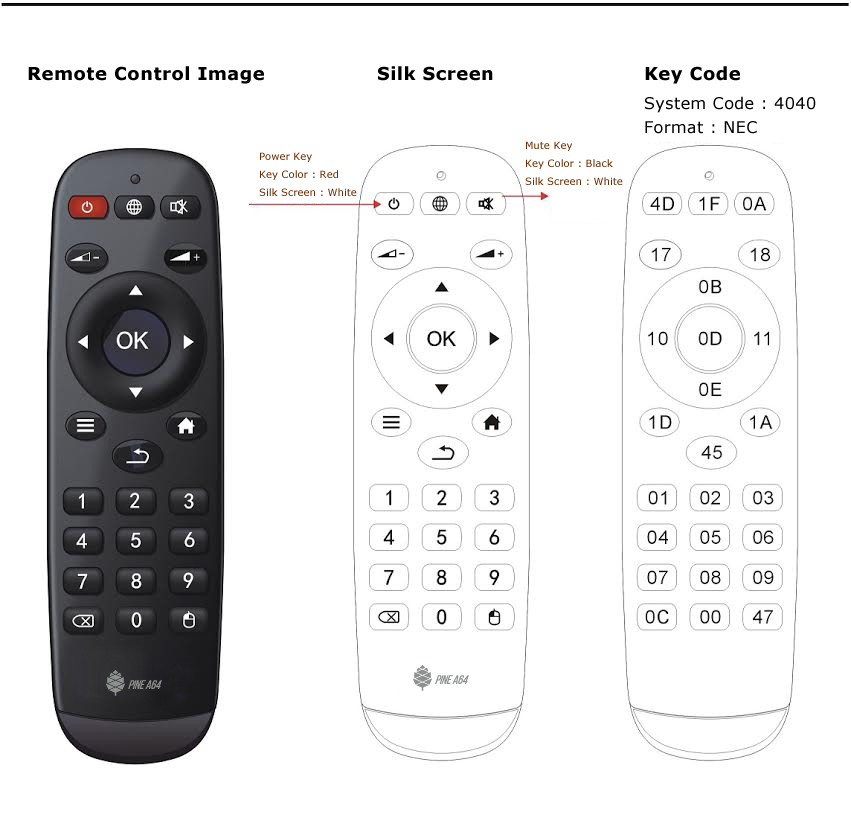
- Remote control button mapping
Pine A64 POT
Other Resources
- Linux Sunxi Wiki page on PINE A64
- Collection of scripts to set up a minimal Xenial 14.04.3 / Debian 8 Jessie root filesystem Contributed By Uli Middelberg
- Linux Image created by Andre Przywara
- PINE A64 with HypriotOS by Dieter and Govinda
- H2testw 1.4 – Gold Standard In Detecting USB Counterfeit Drives
- F3 - an alternative to h2testw
- Benchmarking The Low-Cost PINE 64+ ARM Single Board Computer by Michael Larabel
- PINE64 Linux build scripts, tools and instructions by Longsleep
- PINE64 Linux image by Longsleep
- A series of Youtube video on PINE A64 Developers Board by Michael Larson
- PINE64 Quick Start Guide (with Gotchas)
- Shrinking images on Linux by FrozenCow
- Manjaro Arm installation script