Difference between revisions of "ROCKPro64"
(Added WIFI tips.) |
(→PCIe probe failures on Linux kernel boot: Cleaned up) |
||
| (25 intermediate revisions by 3 users not shown) | |||
| Line 1: | Line 1: | ||
[[File:ROCKPro64v21FRONT.jpg|400px|thumb|right|The ROCKPro64]] | [[File:ROCKPro64v21FRONT.jpg|400px|thumb|right|The ROCKPro64]] | ||
The '''ROCKPro64''' is the most powerful | The '''ROCKPro64''' is the most powerful single-board computer released by PINE64. It is powered by a Rockchip RK3399 hexa-core (dual ARM Cortex A72 and quad ARM Cortex A53) 64-bit processor with a Mali T-860 quad-core GPU. The key features include a PCI Express (PCIe) x4 open-ended slot, the use of LPDDR4 DRAM, and industry-standard heatsink mounting holes. | ||
The ROCKPro64 is equipped with | The ROCKPro64 is equipped with 2 or 4 GB of LPDDR4 system memory, and 128 Mb of SPI boot flash. There is also an optional eMMC module (up to 128 GB) and microSD slot for booting. The board is equipped with 1x USB 3.0 Type-C host port with DP 1.2, 1x USB 3.0 Type-A host port, 2x USB 2.0 host port, Gigabit Ethernet, PI-2 GPIO bus, MiPi DSI interface, eDP interface, touch panel interface, stereo MiPi CSI interface, as well as many other device interfaces such as UART, SPI, I<sup>2</sup>C, for makers to integrate with sensors and other peripherals. Many different operating systems (OSes) are freely available from the open-source community, such as Linux (Ubuntu, Debian, Arch), BSD and Android. | ||
== Getting Started == | == Getting Started == | ||
| Line 66: | Line 66: | ||
| style="text-align: center;" | - || CON16 || GND PWR RST GND || style="text-align: center;" | 4 || Power & reset, unpopulated<br>header near Headphone jack | | style="text-align: center;" | - || CON16 || GND PWR RST GND || style="text-align: center;" | 4 || Power & reset, unpopulated<br>header near Headphone jack | ||
|- | |- | ||
| style="text-align: center;" | 14 || U29 || EMMC || style="text-align: center;" | 34 || eMMC connector | | style="text-align: center;" | 14 || U29 || EMMC || style="text-align: center;" | 34 || eMMC connector<br />(Note: Some datasheets indicate a low<br />supported number of mating cycles.) | ||
|- | |- | ||
| style="text-align: center;" | 14* || J13 || || style="text-align: center;" | 13 || TF-card, a.k.a. microSD<br>(* under 14 on the bottom side) | | style="text-align: center;" | 14* || J13 || || style="text-align: center;" | 13 || TF-card, a.k.a. microSD<br>(* under 14 on the bottom side) | ||
| Line 233: | Line 233: | ||
=== Storage === | === Storage === | ||
* microSD - bootable, | * microSD - bootable, supports SDHC and SDXC | ||
* eMMC - bootable (optional eMMC | * eMMC - bootable (optional eMMC module) | ||
* | * 1x USB 3.0 host port | ||
* | * 1x USB Type-C OTG port with alternate mode DP output | ||
* 2 | * 2x USB 2.0 dedicated host port | ||
=== Expansion Ports === | === Expansion Ports === | ||
* 2x20 pins "Pi2" GPIO | * 2x20 pins "Pi2" GPIO header | ||
* | * PCI Express 2.1 x4 (four full-duplex lanes) open-ended port, [https://git.kernel.org/pub/scm/linux/kernel/git/torvalds/linux.git/commit/?id=712fa1777207 limited] to the Gen1 speed | ||
==== GPIO Pins ==== | ==== GPIO Pins ==== | ||
| Line 398: | Line 398: | ||
| | | | ||
| Maybe [https://github.com/avafinger/pine64-touchscreen this] will help get this working? | | Maybe [https://github.com/avafinger/pine64-touchscreen this] will help get this working? | ||
| [https://pine64.com/?product=7-lcd-touch-screen-panel | | [https://pine64.com/?product=7-lcd-touch-screen-panel 7-inch LCD Touch Screen Panel] | ||
|- | |- | ||
| Wireless | | Wireless | ||
| Line 408: | Line 408: | ||
| | | | ||
| For the "new" ROCKPro64 WIFI module: Verified with Manjaro ARM (kernel 6.2.5). A config file ("firmware file") is needed at <code>/lib/firmware/brcm/brcmfmac43455-sdio.txt</code>. See [[#Getting wifi working ("new" wifi module)]] for the file contents and details. | | For the "new" ROCKPro64 WIFI module: Verified with Manjaro ARM (kernel 6.2.5). A config file ("firmware file") is needed at <code>/lib/firmware/brcm/brcmfmac43455-sdio.txt</code>. See [[#Getting wifi working ("new" wifi module)]] for the file contents and details. | ||
| In 0.7.9 Ayufan linux releases this is deliberately disabled for stability reasons. | | In 0.7.9 Ayufan linux releases this is deliberately disabled for stability reasons. On Manjaro ARM (kernel 6.2.5), WIFI seems to be stable with the firmware file. On a 5GHz network (802.11AC), it is possible to get about 120Mbps using the "new" ROCKPro64 WIFI module. | ||
| [https://store.pine64.org/product/rockpro64-1x1-dual-band-wifi-802-11acbluetooth-5-0-module ROCKPro64 1x1 Dual Band WiFi 802.11AC / Bluetooth 5.0 Module] | | [https://store.pine64.org/product/rockpro64-1x1-dual-band-wifi-802-11acbluetooth-5-0-module ROCKPro64 1x1 Dual Band WiFi 802.11AC / Bluetooth 5.0 Module] | ||
|- | |- | ||
| Line 507: | Line 507: | ||
| | | | ||
| N/A | | N/A | ||
| Ventilation does not exist, thus requires manual changes to add venting. Case should be modified to account power adapter not being centered in cut holes. Opening the case once close without modifying it first is | | Ventilation does not exist, thus requires manual changes to add venting. Case should be modified to account power adapter not being centered in cut holes. Opening the case once close without modifying it first is nearly impossible without special tools. Graphene heatsink is included and does well for Linux but not Android. | ||
| https://pine64.com/?product=rockpro64-playbox-enclosure | | [https://pine64.com/?product=rockpro64-playbox-enclosure ROCKPro64 Playbox Enclosure] | ||
|- | |- | ||
| ROCKPro64 30mm Tall Profile Heatsink | | ROCKPro64 30mm Tall Profile Heatsink | ||
| Line 517: | Line 517: | ||
| N/A | | N/A | ||
| | | | ||
| https:// | | [https://pine64.com/product/rockpro64-30mm-tall-profile-heatsink/ ROCKPro64 30 mm Tall-Profile Heatsink] | ||
|- | |- | ||
| ROCKPro64 20mm Mid Profile Heatsink | | ROCKPro64 20mm Mid Profile Heatsink | ||
| Line 526: | Line 526: | ||
| N/A | | N/A | ||
| | | | ||
| https://pine64.com/?product=rockpro64-20mm-mid-profile-heatsink | | [https://pine64.com/?product=rockpro64-20mm-mid-profile-heatsink ROCKPro64 20 mm Mid-Profile Heatsink] | ||
|- | |- | ||
| Fan For ROCKPro64 20mm Mid Profile Heatsink | | Fan For ROCKPro64 20mm Mid Profile Heatsink | ||
| Line 535: | Line 535: | ||
| N/A | | N/A | ||
| You might want to use [https://github.com/tuxd3v/fanctl fanctl] to control the fan while keeping your CPU cool | | You might want to use [https://github.com/tuxd3v/fanctl fanctl] to control the fan while keeping your CPU cool | ||
| https://pine64.com/?product=fan-for-rockpro64-20mm-mid-profile-heatsink | | [https://pine64.com/?product=fan-for-rockpro64-20mm-mid-profile-heatsink Fan For ROCKPro64 20 mm Mid-Profile Heatsink] | ||
|- | |- | ||
| HDMI output 4K@60Hz | | HDMI output 4K@60Hz | ||
| Line 546: | Line 546: | ||
| | | | ||
|- | |- | ||
| | | PCI Express 2.1 | ||
| | | | ||
| | | | ||
| Line 553: | Line 552: | ||
| | | | ||
| | | | ||
| The PCI Express interface of the RK3399 [https://git.kernel.org/pub/scm/linux/kernel/git/torvalds/linux.git/commit/?id=712fa1777207 is limited] to the Gen1 speed. As a result, some installed PCI Express devices may operate with degraded performance, such as M.2 SSDs that support fewer than four PCI Express lanes, installed using an adapter like [https://pine64.com/product/rockpro64-pci-e-x4-to-m-2-ngff-nvme-ssd-interface-card/ this one]. | |||
| | | | ||
|- | |- | ||
| Line 562: | Line 562: | ||
| | | | ||
| | | | ||
| https:// | | [https://pine64.com/product/rtc-backup-battery-holder-cr-2032/ RTC Backup Battery Holder CR2032] | ||
|- | |- | ||
| Boot from USB/PXE | | Boot from USB/PXE | ||
| Line 577: | Line 577: | ||
== Board Information, Schematics and Certifications == | == Board Information, Schematics and Certifications == | ||
* Board | * Board dimensions: 133 mm x 80 mm x 19 mm | ||
* | * Power input: 12 V, 3 A or 5 A, using 5.5 mm (OD) / 2.1 mm (ID) type M barrel DC connector | ||
* [https://files.pine64.org/doc/rockpro64/rockpro64_v21-SCH.pdf ROCKPro64 Schematic v2.1 (Second Batch Production Release)] | * [https://files.pine64.org/doc/rockpro64/rockpro64_v21-SCH.pdf ROCKPro64 Schematic v2.1 (Second Batch Production Release)] | ||
** [https://files.pine64.org/doc/rockpro64/RockPro64_v21_Boardoutline-top.dxf ROCKPro64 v2.1 Board Top Outline in AutoCad DXF format] | ** [https://files.pine64.org/doc/rockpro64/RockPro64_v21_Boardoutline-top.dxf ROCKPro64 v2.1 Board Top Outline in AutoCad DXF format] | ||
| Line 585: | Line 585: | ||
** [https://files.pine64.org/doc/rockpro64/RockPro64_v21_Boardoutline-bottom.pdf ROCKPro64 v2.1 Board Bottom Outline in PDF format] | ** [https://files.pine64.org/doc/rockpro64/RockPro64_v21_Boardoutline-bottom.pdf ROCKPro64 v2.1 Board Bottom Outline in PDF format] | ||
* [https://files.pine64.org/doc/rockpro64/rockpro64_v20-SCH.pdf ROCKPro64 Schematic v2.0 (Pilot Production Release)] | * [https://files.pine64.org/doc/rockpro64/rockpro64_v20-SCH.pdf ROCKPro64 Schematic v2.0 (Pilot Production Release)] | ||
** [http://files.pine64.org/doc/rockpro64/Rockpro64-ver2.0-topsilk_ref.pdf ROCKPro64 v2.0 Board Top Silkscreen in PDF format] (contains component labels) | |||
** [https://files.pine64.org/doc/rockpro64/ROCKPRo64%20Engineering%20Change%20Notice%2020180628RP01.pdf Engineering Change Notice for v2.0 to turn on 3.3V power on PCIe] | ** [https://files.pine64.org/doc/rockpro64/ROCKPRo64%20Engineering%20Change%20Notice%2020180628RP01.pdf Engineering Change Notice for v2.0 to turn on 3.3V power on PCIe] | ||
* [https://files.pine64.org/doc/rockpro64/rockpro64_wifi_ap6359SA.pdf ROCKPro64 AP6359SA Wifi/BT Schematic] | * [https://files.pine64.org/doc/rockpro64/rockpro64_wifi_ap6359SA.pdf ROCKPro64 AP6359SA Wifi/BT Schematic] | ||
| Line 657: | Line 658: | ||
* [https://stikonas.eu/wordpress/2019/09/15/blobless-boot-with-rockpro64/ Blobless boot with RockPro64 by Andrius Štikonas] | * [https://stikonas.eu/wordpress/2019/09/15/blobless-boot-with-rockpro64/ Blobless boot with RockPro64 by Andrius Štikonas] | ||
* [https://marcin.juszkiewicz.com.pl/2020/06/17/ebbr-on-rockpro64/ EBBR on RockPro64 by Marcin Juszkiewicz] | * [https://marcin.juszkiewicz.com.pl/2020/06/17/ebbr-on-rockpro64/ EBBR on RockPro64 by Marcin Juszkiewicz] | ||
* [[ROCKPro64 Device Tree Overlays on Mainline]] | * [[ROCKPro64 Device Tree Overlays on Mainline]] | ||
* [[ROCKPro64 Hardware Tweaks]] | |||
== The NAS Case for the ROCKPro64 == | == The NAS Case for the ROCKPro64 == | ||
| Line 705: | Line 705: | ||
If you can log in through serial but don't get any video or GPU acceleration on Debian, this is likely due to Debian's decision to compile the devfreq governors as loadable modules but not including them early enough for panfrost to be able to be provided with one of them. | If you can log in through serial but don't get any video or GPU acceleration on Debian, this is likely due to Debian's decision to compile the devfreq governors as loadable modules but not including them early enough for panfrost to be able to be provided with one of them. | ||
The usual sign of this being the case is the following line in | The usual sign of this being the case is the following line in the kernel log: <code>[drm:panfrost_devfreq_init [panfrost]] *ERROR* Couldn't initialize GPU devfreq</code> | ||
To fix this issue, run the following as <code>root</code> and reboot: | |||
- | echo governor_simpleondemand >> /etc/initramfs-tools/modules | ||
update-initramfs -u -k $(uname -r) | |||
=== PCIe probe failures on Linux kernel boot === | |||
While booting the Linux kernel, you might experience PCIe probe failures, which render the attached PCIe device inaccessible. The [https://lore.kernel.org/all/20230509153912.515218-1-vincenzopalazzodev@gmail.com/ "drivers: pci: introduce configurable delay for Rockchip PCIe bus scan"] thread on the Linux kernel mailing list (LKML) discusses this issue and proposes a fix. | |||
Manjaro ARM applies the following patches to the kernel package, which fix the issue: | |||
* [https://gitlab.manjaro.org/manjaro-arm/packages/core/linux/-/blob/44e81d83b7e002e9955ac3c54e276218dc9ac76d/1005-rk3399-rp64-pcie-Reimplement-rockchip-PCIe-bus-scan-delay.patch 1005-rk3399-rp64-pcie-Reimplement-rockchip-PCIe-bus-scan-delay.patch] | |||
* [https://gitlab.manjaro.org/manjaro-arm/packages/core/linux/-/blob/44e81d83b7e002e9955ac3c54e276218dc9ac76d/1007-arm64-dts-rockchip-Add-PCIe-bus-scan-delay-to-RockPr.patch 1007-arm64-dts-rockchip-Add-PCIe-bus-scan-delay-to-RockPr.patch] | |||
[[Category:ROCKPro64]] [[Category:Rockchip RK3399]] | [[Category:ROCKPro64]] | ||
[[Category:Rockchip RK3399]] | |||
Latest revision as of 04:41, 18 November 2023

The ROCKPro64 is the most powerful single-board computer released by PINE64. It is powered by a Rockchip RK3399 hexa-core (dual ARM Cortex A72 and quad ARM Cortex A53) 64-bit processor with a Mali T-860 quad-core GPU. The key features include a PCI Express (PCIe) x4 open-ended slot, the use of LPDDR4 DRAM, and industry-standard heatsink mounting holes.
The ROCKPro64 is equipped with 2 or 4 GB of LPDDR4 system memory, and 128 Mb of SPI boot flash. There is also an optional eMMC module (up to 128 GB) and microSD slot for booting. The board is equipped with 1x USB 3.0 Type-C host port with DP 1.2, 1x USB 3.0 Type-A host port, 2x USB 2.0 host port, Gigabit Ethernet, PI-2 GPIO bus, MiPi DSI interface, eDP interface, touch panel interface, stereo MiPi CSI interface, as well as many other device interfaces such as UART, SPI, I2C, for makers to integrate with sensors and other peripherals. Many different operating systems (OSes) are freely available from the open-source community, such as Linux (Ubuntu, Debian, Arch), BSD and Android.
Getting Started
The article ROCKPro64 Getting Started gives important information to get the board up and running.
Software releases
In the ROCKPro64 Software Releases page, you will find a complete list of currently supported Operating System images that work with the ROCKPro64, as well as other related software. The Software Release page has links to download the images as well as high level instructions to load each image.
Please see the Getting started page for detailed discussion of what you need (prerequisites) as well as instructions if the high level instructions are insufficient.
Board Layout


Main Chips
- RK3399 system-on-chip (1)
- LPDDR4 SDRAM 1 (18)
- LPDDR4 SDRAM 2 (3)
- SPI NOR flash memory (17)
- RK808 power management (near 19)
- RTL8211 ethernet transceiver (near 25)
- ES8316 Sound Codec (on rear of board)
- The heatsink mounting holes around the RK3399 are 59 mm apart
Switches
The Power button (11, SW3): is the same as on your mobile phone - press and release after about 1 second to power on. Press and hold for about 3 seconds to power off.
The Reset button (10, SW901): performs a reset.
The Recover button (28, SW900): used to enter maskrom mode.
Connectors, Sockets and Headers
| Diagram | Schematic designator |
Silkscreen label |
Number of pins |
Description |
|---|---|---|---|---|
| 2 | U39 | PI-2-bus | 40 | Pi-2 bus |
| 4 | J8 | +FAN- | 2 | PWM controlled fan header |
| 5 | J10 | SPDIF | 3 | SPDIF header |
| 6 | U6 | +RTC- | 2 | RTC battery backup header |
| 7 | U31 | Wifi-BT | 16 | SDIO WIFI/BT module-MIMO 2 |
| 8 | USB3 | 9 | USB-3 and USB Type C | |
| 9 | USB1 | 2×4 | Dual USB-2 | |
| 12 | IR1 | IR | 3 | infrared receiver socket |
| 13 | J16 | Headphone+mic | 4 | Headphone + mic 3.5mm jack |
| - | CON16 | GND PWR RST GND | 4 | Power & reset, unpopulated header near Headphone jack |
| 14 | U29 | EMMC | 34 | eMMC connector (Note: Some datasheets indicate a low supported number of mating cycles.) |
| 14* | J13 | 13 | TF-card, a.k.a. microSD (* under 14 on the bottom side) | |
| 15 | U30 | 14 | SDIO WIFI/BT module-MIMO 1 | |
| 16 | SW4 | 2 | Jumper to #Disable eMMC | |
| 19 | J15 | PCI | 64 | PCI-express X4 socket |
| 20 | J21 | DSI | 30 | DSI |
| 21 | J22 | EDP | 30 | LCD EDP |
| 22 | CON1 | TP | 6 | touch panel connector |
| 23 | CON15 | 4 | DC out for SATA disk cable (direct connect from DC-IN) | |
| 24 | J11 | DC-IN | 2 | Power input, positive tip; 12V/3A (minimum) recommended |
| 25 | U32 | 8 | 8P8C (often referred to as 'RJ45') | |
| 26 | J14 | 19 | HDMI | |
| 27 | J17 | MIPI CAM | 32 | MIPI-1 |
| 29 | J19 | MIPI CAM | 32 | MIPI-2 |
| 30 | J18 | CIF | 26 | CIF |
LEDs
A green LED next to the 12V input barrel connector will light as long as there is 12V applied to the connector. (Even if the RockPro64 is powered off.)
A white LED behind the reset button will light as long as the RockPro64 is running (it comes on a few seconds after power on, when control is passed to the operating system.)
A red LED behind the reset button is DIY - it is lit for example if the board is in OTG mode with an Ayufan image, or if an Android image is in standby mode.
Yellow and green LEDs on the LAN socket behave in a standard way.
Jumpers
They are used for boot device selection, as described in the following section.
Disable eMMC
There is an unlabelled (on the PCB silk-screen) 2-pin jumper (16) between the eMMC socket (14) and the SPI chip (17). It is designated as SW4 on the schematic diagram. The default condition is OPEN (no jumper). It is useful for controlling the boot as follows:
Default boot device (with no SPI software) is eMMC, then SDcard. If both the eMMC and the SDcard contain bootable images then the eMMC can be disabled by installing the jumper. This completely removes the eMMC from the resulting OS. If you wish the eMMC to be visible in the booted OS the jumper should be removed 2 seconds after applying power (and before the white LED comes on).
The possible combinations are summarised in the table below.
- 1 = present
- 0 = not present
| µSD | eMMC | SW4 | boot from |
|---|---|---|---|
| 0 | 0 | 0 | unsupported |
| 0 | 0 | 1 | unsupported |
| 0 | 1 | 0 | eMMC |
| 0 | 1 | 1 | unsupported |
| 1 | 0 | 0 | SDCard |
| 1 | 0 | 1 | SDCard |
| 1 | 1 | 0 | eMMC |
| 1 | 1 | 1 | SDCard |
Disable SPI (while booting)
There is a second possibility to jumper your ROCKPro64: If you mess-up your SPI and are unable to boot, jumpering pins 23 (CLK) and 25 pin (GND) on the PI-2-bus header will disable the SPI as a boot device. (This was taken from the IRC logs, 09 August 2018 @ 17:23) You have to remove the jumper 2 seconds after having started your RP64 (before the white LED turns ON) otherwise the SPI will be missing and you won't be able to flash it. Ayufan images contain (at the moment) only one script for the SPI and the RP64, it's "rockpro64_reset_spi_flash". Other SPI scripts are dedicated to the R64 (as it is written on the name) and it will mess-up your RP64 SPI if you use them.
Hardware Compatibility
The hardware compatibility list can be found under ROCKPro64 Hardware compatibility.
Board Features
This section outlines the most important characteristics of the board and its components.
SoC and Memory Specification
- Based on Rockchip RK3399

CPU Architecture
- Dual-core Cortex-A72 up to 2.0GHz CPU
- Quad-core Cortex-A53 up to 1.5GHz CPU
- big.LITTLE architecture: Dual Cortex-A72 + Quad Cortex-A53, 64-bit CPU
- Cortex-A72:
- 1-4x Symmetrical Multiprocessing (SMP) within a single processor cluster, and multiple coherent SMP processor clusters through AMBA 5 CHI or AMBA 4 ACE technology
- AArch64 for 64-bit support and new architectural features
- L1 cache 48KB Icache and 32KB Dcache for each A72
- L2 cache 1024KB for big cluster
- DSP & SIMD extensions
- VFPv4 floating point
- Hardware virtualization support
- Cortex-A53:
- L1 cache 32KB Icache and 32KB Dcache for each A53
- L2 cache 512KB for little cluster
- Full implementation of the ARM architecture v8-A instruction set
- ARM Neon Advanced SIMD (single instruction, multiple data) support for accelerated media and signal processing computation
- ARMv8 Cryptography Extensions
- In-order pipeline with symmetric dual-issue of most instructions
- Include VFP v3 hardware to support single and double-precision operations
- TrustZone technology support
- Full CoreSight debug solution
- One isolated voltage domain to support DVFS
GPU Architecture
- ARM Mali-T860MP4 Quad-core GPU
- The highest performance GPUs built on Arm Mali’s famous Midgard architecture, the Mali-T860 GPU is designed for complex graphics use cases and provides stunning visuals for UHD content.
- Frequency: 650MHz
- Throughput: 1300Mtri/s, 10.4Gpix/s
- OpenGL® ES 1.1, 1.2, 2.0, 3.1, 3.2, Vulkan 1.0*, OpenCL™ 1.1, 1.2, DirectX® 11 FL11_1, RenderScript™.
System Memory
- LPDDR4 RAM Memory Variants: Dual Channels 2GB and 4GB.
- Storage Memory: 128Mb built-in SPI Flash memory (as at August 2018 only support for USB boot).
Display
- Dual VOP: one supports resolutions up to 4096x2160 and AFBC; the other supports resolutions up to 2560x1600
- Dual channel MIPI-DSI (4 lanes per channel)
- eDP 1.3 (4 lanes with 10.8Gbps) to support displays, with PSR
- Digital Video port up to 4Kp60
- DisplayPort 1.2 (4 lanes, up to 4K 60Hz)
- Supports Rec.2020 and conversion to Rec.709
Video
- Digital Video output up to 4K@60Hz
- 4K HDR @ 30fps
- H.264/AVC Base/Main/High/High10 profile @ level 5.1; up to 4Kx2K @ 60fps
- H.265/HEVC Main/Main10 profile @ level 5.1 High-tier; up to 4Kx2K @ 60fps
- VP9, up to 4Kx2K @ 60fps
- MPEG-1, ISO/IEC 11172-2, up to 1080P @ 60fps
- MPEG-2, ISO/IEC 13818-2, SP@ML, MP@HL, up to 1080P @ 60fps
- MPEG-4, ISO/IEC 14496-2, SP@L0-3, ASP@L0-5, up to 1080P @ 60fps
- VC-1, SP@ML, MP@HL, AP@L0-3, up to 1080P @ 60fps
- MVC is supported based on H.264 or H.265, up to 1080P @ 60fps
Audio
- 3.5mm Phone Jack
- 3-pin S/PDIF header
- Audio via Digital Video port
Camera
- Dual MIPI CSI,dual ISP, maximum input resolution of 13M pixels
Network
- 10/100/1000Mbps Ethernet - Capable of pushing 941 MBit/s in iperf3
- Wi-Fi 802.11 ac/a/b/g/n with Bluetooth 4.01 (old version with 2x2) / Bluetooth 5 (new version with 1x1) (optional)
Storage
- microSD - bootable, supports SDHC and SDXC
- eMMC - bootable (optional eMMC module)
- 1x USB 3.0 host port
- 1x USB Type-C OTG port with alternate mode DP output
- 2x USB 2.0 dedicated host port
Expansion Ports
- 2x20 pins "Pi2" GPIO header
- PCI Express 2.1 x4 (four full-duplex lanes) open-ended port, limited to the Gen1 speed
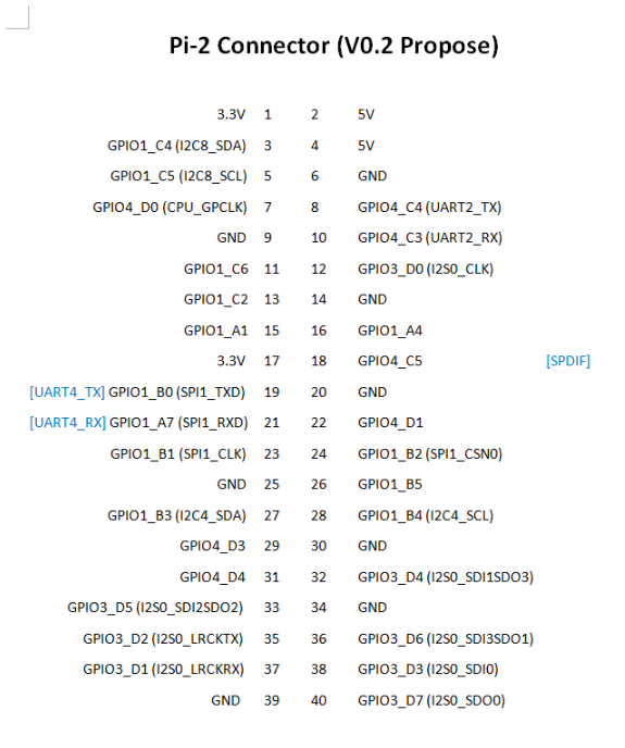
GPIO Pins
| Assigned To | Pin Nr. | Pin Nr. | Assigned To |
|---|---|---|---|
| 3.3 V | 1 | 2 | 5 V |
| GPIO1_C4 (I2C8_SDA) a | 3 | 4 | 5 V |
| GPIO1_C5 (I2C8_SCL) a | 5 | 6 | GND |
| GPIO4_D0 (CPU_GPCLK) | 7 | 8 | GPIO4_C4 (UART2_TX) |
| GND | 9 | 10 | GPIO4_C3 (UART2_RX) |
| GPIO1_C6 | 11 | 12 | GPIO3_D0 (I2S0_CLK) |
| GPIO1_C2 | 13 | 14 | GND |
| GPIO1_A1 | 15 | 16 | GPIO1_A4 |
| 3.3 V | 17 | 18 | GPIO4_C5 [SPDIF] |
| [UART4_TX] GPIO1_B0 (SPI1_TXD) | 19 | 20 | GND |
| [UART4_RX] GPIO1_A7 (SPI1_RXD) | 21 | 22 | GPIO4_D1 |
| GPIO1_B1 (SPI1_CLK) | 23 | 24 | GPIO1_B2 (SPI1_CSN0) |
| GND | 25 | 26 | GPIO1_B5 |
| GPIO1_B3 (I2C4_SDA) | 27 | 28 | GPIO1_B4 (I2C4_SCL) |
| GPIO4_D3 | 29 | 30 | GND |
| GPIO4_D4 | 31 | 32 | GPIO3_D4 (I2S0_SDI1SDO3) |
| GPIO3_D5 (I2S0_SDI2SDO2) | 33 | 34 | GND |
| GPIO3_D2 (I2S0_LRCKTX) | 35 | 36 | GPIO3_D6 (I2S0_SDI3SDO1) |
| GPIO3_D1 (I2S0_LRCKRX) | 37 | 38 | GPIO3_D3 (I2S0_SDI0) |
| GND | 39 | 40 | GPIO3_D7 (I2S0_SDO0) |
Notes
- a: pulled high to 3.3V through 2.2kOhm resistor
Linux /dev/gpiochip Assignments
| Pin Nr. | 3 | 5 | 7 | 8 | 10 | 11 | 12 | 13 | 15 | 16 | 18 | 19 | 21 | 22 | 23 | 24 | 26 | 27 | 28 | 29 | 31 | 32 | 33 | 35 | 36 | 37 | 38 | 40 |
|---|---|---|---|---|---|---|---|---|---|---|---|---|---|---|---|---|---|---|---|---|---|---|---|---|---|---|---|---|
| Chip | 1 | 1 | 4 | 4 | 4 | 1 | 3 | 1 | 1 | 1 | 4 | 1 | 1 | 4 | 1 | 1 | 1 | 1 | 1 | 4 | 4 | 3 | 3 | 3 | 3 | 3 | 3 | 3 |
| Line | 20 | 21 | 24 | 20 | 19 | 22 | 24 | 18 | 1 | 4 | 21 | 8 | 7 | 25 | 9 | 10 | 13 | 11 | 12 | 27 | 28 | 28 | 29 | 26 | 30 | 25 | 27 | 31 |
On Linux, using the new /dev/gpiochip API, the n in GPIOn_XX appears to correlate to the number of the /dev/gpiochipn, and the XX to the definition RK_PXX of lines in include/dt-bindings/pinctrl/rockchip.h of the Linux kernel source. Having these named in the dts would be nice.
You can use libgpiod to drive them, and test them with the included tools (gpioinfo, gpioset, ...)
For example, gpioset 4 25=1 (run as root) would turn pin 22 on. Do beware that poking the wrong GPIO pin can lock up your system.
The conversion table at right is also available as a C header file.
Working Features
| Feature/Option | Android | Android Version | Linux | Linux Version | Test/Verify Steps | Notes | Product Link |
|---|---|---|---|---|---|---|---|
| PINE64 LCD Touchscreen (Screen/Touch) | Yes/Yes | No/No | Maybe this will help get this working? | 7-inch LCD Touch Screen Panel | |||
| Wireless
ROCKPro64 2×2 MIMO Dual Band WiFi 802.11AC / Bluetooth 4.2 Module (old) ROCKPro64 1x1 Dual Band WiFi 802.11AC / Bluetooth 5.0 Module (new) |
Yes/Yes | No/Yes* | For the "new" ROCKPro64 WIFI module: Verified with Manjaro ARM (kernel 6.2.5). A config file ("firmware file") is needed at /lib/firmware/brcm/brcmfmac43455-sdio.txt. See #Getting wifi working ("new" wifi module) for the file contents and details.
|
In 0.7.9 Ayufan linux releases this is deliberately disabled for stability reasons. On Manjaro ARM (kernel 6.2.5), WIFI seems to be stable with the firmware file. On a 5GHz network (802.11AC), it is possible to get about 120Mbps using the "new" ROCKPro64 WIFI module. | ROCKPro64 1x1 Dual Band WiFi 802.11AC / Bluetooth 5.0 Module | ||
| USB OTG | use this script: rockpro64_enable_otg.sh, then configure ip on usb0: ifconfig usb0 169.169.222.222 and run iperf, you should likely see about 200-300MB/s | ROCKPro64#OTG_mode | |||||
| USB Mass Storage USB2/USB3 | Yes/yes | Yes/Yes | |||||
| Dedicated Fan Power (pwm1) | Yes | You might want to use ATS. | |||||
| GPIO pins (raw or via RPI python scripts) | Check out what Frank Mankel has done. | ||||||
| MIPI CSI Camera 1 and 2 | |||||||
| eDP | |||||||
| HDMI Audio | Yes | 7.1.2 | Yes | 4.4.132-1083 - 4.4.138-1100 | Stopped working in 4.4.154.1105. Ayufan is looking into it. This is working in Manjaro ARM (kernel 6.2.5). Select the Analog Output (Built-in Audio Stereo) option in the audio output device selection window (either use pavucontrol or the volume button in the KDE desktop). Despite the slightly misleading name, audio does go through the HDMI port. See here for details: https://forum.manjaro.org/t/no-hdmi-audio-on-rockpro64/25595/2.
|
||
| 3.5mm Audio/Mic | |||||||
| USB-C Host | |||||||
| Display via USB-C | Yes | 7.x and 8.x | eDP via USB-C per tillim. No sound on Android 7.x. Sound does work on Android 8.x | ||||
| ROCKPro64 PLAYBOX ENCLOSURE | N/A | N/A | N/A | Ventilation does not exist, thus requires manual changes to add venting. Case should be modified to account power adapter not being centered in cut holes. Opening the case once close without modifying it first is nearly impossible without special tools. Graphene heatsink is included and does well for Linux but not Android. | ROCKPro64 Playbox Enclosure | ||
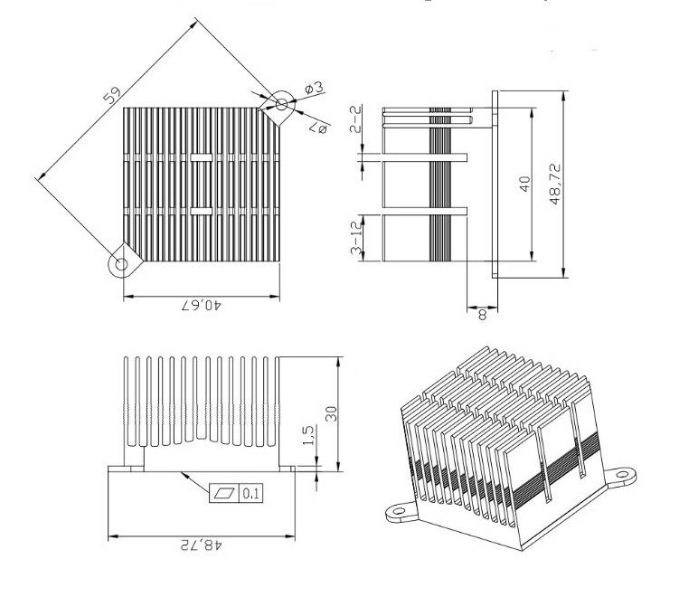
| ROCKPro64 30mm Tall Profile Heatsink | N/A | N/A | N/A | ROCKPro64 30 mm Tall-Profile Heatsink | |||
| ROCKPro64 20mm Mid Profile Heatsink | N/A | N/A | N/A | ROCKPro64 20 mm Mid-Profile Heatsink | |||
| Fan For ROCKPro64 20mm Mid Profile Heatsink | N/A | N/A | N/A | You might want to use fanctl to control the fan while keeping your CPU cool | Fan For ROCKPro64 20 mm Mid-Profile Heatsink | ||
| HDMI output 4K@60Hz | |||||||
| PCI Express 2.1 | The PCI Express interface of the RK3399 is limited to the Gen1 speed. As a result, some installed PCI Express devices may operate with degraded performance, such as M.2 SSDs that support fewer than four PCI Express lanes, installed using an adapter like this one. | ||||||
| Real Time Clock (RTC) battery backup | RTC Backup Battery Holder CR2032 | ||||||
| Boot from USB/PXE |
RockChip themselves have tables of supported features at 4.4 and mainline kernel versions in their wiki here.
Board Information, Schematics and Certifications
- Board dimensions: 133 mm x 80 mm x 19 mm
- Power input: 12 V, 3 A or 5 A, using 5.5 mm (OD) / 2.1 mm (ID) type M barrel DC connector
- ROCKPro64 Schematic v2.1 (Second Batch Production Release)
- ROCKPro64 Schematic v2.0 (Pilot Production Release)
- ROCKPro64 v2.0 Board Top Silkscreen in PDF format (contains component labels)
- Engineering Change Notice for v2.0 to turn on 3.3V power on PCIe
- ROCKPro64 AP6359SA Wifi/BT Schematic
- ROCKPro64 Pi-2 Pin assignment and definition
- ROCKPro64 3D model
Certifications:
- Disclaimer: Please note that PINE64 SBC is not a "final" product and in general certification is not necessary. However, PINE64 still submit the SBC for FCC, CE, and ROHS certification and obtain the certificates to proof that SBC board is capable on passing the testing. Please note a final commercial product needs to performs its owns testing and obtains its owns certificates.
- ROCKPro64 FCC Certificate
- ROCKPro64 CE Certificate
- ROCKPro64 RoHS Report
Datasheets for Components and Peripherals
Rockchip RK3399 SoC information:
- Rockchip RK3399 SoC Brief
- Rockchip RK3399 Datasheet V2.1
- Rockchip RK3399 Technical Reference Manual part 1
- Rockchip RK808 Datasheet V0.8
LPDDR4 (200 Balls) SDRAM:
eMMC information:
- PINE64 eMMC module schematic
- PINE64 USB adapter for eMMC module V2 schematic
- PINE64 USB adapter for eMMC module PCB in JPEG
- 16GB Foresee eMMC Datasheet
- 32GB/64GB/128GB SanDisk eMMC Datasheet
SPI NOR Flash information:
Heatsink related info:
Wireless related info:
Ethernet related info:
Peripheral related info:
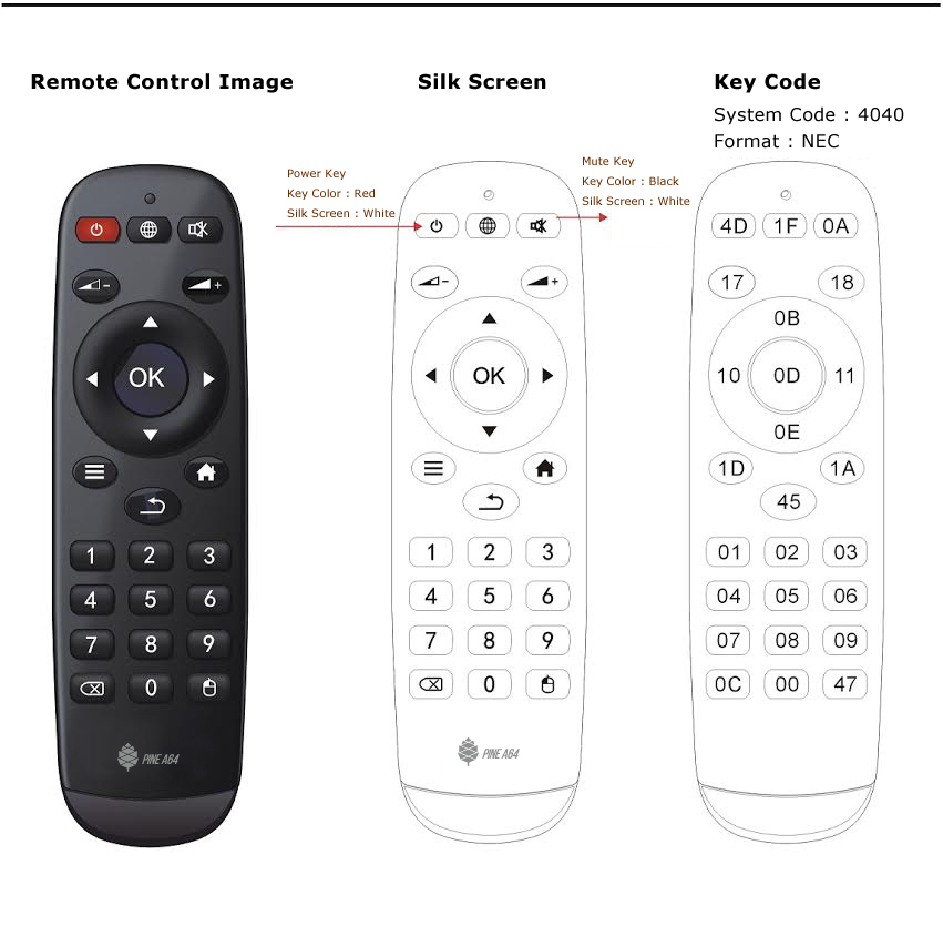
Remote control button mapping:
Audio Codec (ES8316) (under board):
PWM controlled fan, SPDIF, and RTC Battery Backup headers:
Useful Articles and Blog Posts
If you want to dive in to the ecosystem, here's a short list of various articles and blog posts that can help you set up your soft- or hardware development environment.
- Blobless boot with RockPro64 by Andrius Štikonas
- EBBR on RockPro64 by Marcin Juszkiewicz
- ROCKPro64 Device Tree Overlays on Mainline
- ROCKPro64 Hardware Tweaks
The NAS Case for the ROCKPro64

Please follow this this link for detailed instructions on how to assemble the ROCKPro64 NAS Case.
The NAS Case instructions also contains detailed information about:
- what the NAS Case ships with
- What additional things you need to purchase for your NAS Case
- What optional things you can consider purchasing for your NAS build
- What OS Image we recommend you use for your NAS build
- IO accessibility after installing the ROCKPro64 into the NAS Case
- NAS Case Exploded View
- NAS Case Drawing
3D printable ITX mounting brackets

Allows mounting a ROCKPro64-A or Quartz64-A board inside a regular PC case that conforms to the ITX standard, using 3D printed brackets:
- AMF/STL/STEP files plus the original FreeCAD file used to create the models File:RP64-A Q64-A to ITX mounting brackets.zip
- Make sure to flip the two brackets by 180 degrees on one of the horizontal axes (X/Y) in your slicer of choice before printing to avoid unnecessary supports
- To allow enough clearance between the board and the bracket you either need to print four copies of the washer model or add nut(s) between the board and the bracket
- If using nuts for the clearance between the board and the brackets, make sure it creates at least 3.2mm of spacing in between
- Depending on the accuracy and calibration of a 3D printer, slight deviation can occur and you likely need to manually widen some of the holes to allow screws to fit
Other Resources
- ROCKPro64 Forum
- PINE64 shop
- Rockchip Linux GitHub Repo
- Rockchip Open Source Wiki
- ExplainingComputers have a video review of the RockPro64 here, including linux first boot.
- ROCKPro64 Installing Arch Linux ARM
- ROCKPro64 Powering From An ATX Supply
Troubleshooting
No Video or GPU Acceleration on Debian
If you can log in through serial but don't get any video or GPU acceleration on Debian, this is likely due to Debian's decision to compile the devfreq governors as loadable modules but not including them early enough for panfrost to be able to be provided with one of them.
The usual sign of this being the case is the following line in the kernel log: [drm:panfrost_devfreq_init [panfrost]] *ERROR* Couldn't initialize GPU devfreq
To fix this issue, run the following as root and reboot:
echo governor_simpleondemand >> /etc/initramfs-tools/modules
update-initramfs -u -k $(uname -r)
PCIe probe failures on Linux kernel boot
While booting the Linux kernel, you might experience PCIe probe failures, which render the attached PCIe device inaccessible. The "drivers: pci: introduce configurable delay for Rockchip PCIe bus scan" thread on the Linux kernel mailing list (LKML) discusses this issue and proposes a fix.
Manjaro ARM applies the following patches to the kernel package, which fix the issue: