Difference between revisions of "Pinecil Hall Effect Sensor"
Jump to navigation
Jump to search
m (→Hints) |
m (→Images) |
||
| (41 intermediate revisions by 2 users not shown) | |||
| Line 3: | Line 3: | ||
The Hall Effect Sensor (HES) is an optional end user installed sensor that activates to put Pinecil to sleep when it enters a holder or stand. This requires a neodymium magnet attached to the stand. The closer the HES in the Pinecil is to the magnet, the more likely the HES will activate to enter sleep mode. This adds a feature to Pinecil that is often seen in high end pro irons. | The Hall Effect Sensor (HES) is an optional end user installed sensor that activates to put Pinecil to sleep when it enters a holder or stand. This requires a neodymium magnet attached to the stand. The closer the HES in the Pinecil is to the magnet, the more likely the HES will activate to enter sleep mode. This adds a feature to Pinecil that is often seen in high end pro irons. | ||
# Order a Hall Effect Sensor [https://www.lcsc.com/product-detail/Position-Sensor_SILICON-LABS-SI7210-B-00-IVR_C2654956.html (SI7210-B-00 here)], also | == Tools and Supplies == | ||
# Order a Hall Effect Sensor [https://www.lcsc.com/product-detail/Position-Sensor_SILICON-LABS-SI7210-B-00-IVR_C2654956.html (SI7210-B-00 here)], also at Digikey and Mouser. | |||
# Ordering 2-3 might be a good idea in case the first one is damaged during install (if all goes well, one could mail the extras to a friend or another Pine64 member in the community chat ;). | # Ordering 2-3 might be a good idea in case the first one is damaged during install (if all goes well, one could mail the extras to a friend or another Pine64 member in the community chat ;). | ||
# Jeweler's magnifying glasses or magnifying lamp or a microscope is recommended as the [https://madpcb.com/glossary/sot-23/ SOT23] chip is very small. | |||
# Borrow a second soldering iron (this is when 2x Pinecils is a good idea). | # Borrow a second soldering iron (this is when 2x Pinecils is a good idea). | ||
# Get some [https://a.co/d/0jU8zic neodymium magnets], just two 8x2.7mm at 8:00PM and 12:00PM on the stand could be enough. Experimentation is needed. Start with just one small magnet and increase the number | # Get some [https://a.co/d/0jU8zic neodymium magnets], just two 8x2.7mm at 8:00PM and 12:00PM on the stand could be enough. Experimentation is needed. Start with just one small magnet and increase the number placed around the stand until 360° sleep is activated when the Pinecil hits the stand. | ||
# Reference [[Pinecil:_Test,_Repair,_Issues#Schematics_and_Board_Data | Schematics are here]] (search for U14). | |||
# Reference [[Pinecil: | |||
== Videos == | |||
# Easy trick to [https://www.youtube.com/watch?v=aK01V5DrrVk Open Pinecil] | # Easy trick to [https://www.youtube.com/watch?v=aK01V5DrrVk Open Pinecil]. | ||
# | # How to install [https://www.youtube.com/watch?v=vU-fhELpI8Y Hall Sensor video]. | ||
== Installation == | |||
# Updating to the newest firmware before installing is recommended, see the [[Pinecil#Firmware & Updates|Firmware article]]. These instructions are for 2.18 or newer firmware. | # Updating to the newest firmware before installing is recommended, see the [[Pinecil#Firmware & Updates|Firmware article]]. These instructions are for 2.18 or newer firmware. | ||
# The HES is located at the very front of the Pinecil, | # The HES is located at the very front of the Pinecil, where the cartridge enters, see [[#Images|pcb images here]]. | ||
# Once it is soldered, cleaned, and assembled, check the sleep menu, a new hall sensitivity option appears. | # Once it is soldered, cleaned, and assembled, check the sleep menu, a new hall sensitivity option appears. | ||
# See this article on how to set up the [https://github.com/Ralim/IronOS/blob/dev/Documentation/HallSensor.md sensitivity settings] on the firmware menu (Ralim's IronOS). | # See this article on how to set up the [https://github.com/Ralim/IronOS/blob/dev/Documentation/HallSensor.md sensitivity settings] on the firmware menu (Ralim's IronOS). | ||
# | # Once you change the Sleep menu > Hall sensitivity to what you like, then scroll back to the main screen in order for the setting to be saved and persist on reboot. | ||
# Note: IronOS firmware does not flash a setting change until one scrolls out of the sub-menu back to the main screen. This is to reduce the total number of flashes done as several settings might be changed in one section (number of flashes is not unlimited; most users will not encounter the maximum allowed flashes on normal use over years). | |||
== Hints == | |||
# Try not to overheat the sensor while soldering as that could damage it and even cause a leg to fall off. This is a | # Try not to overheat the sensor while soldering as that could damage it and even cause a leg to fall off. | ||
# | # This is a small SOT23 chip. Tacking one pin on the 2-pin side helps to hold it in place before soldering the rest of the sensor. | ||
# Apply | # It is recommended to solder this with an iron with a small tip instead of using hot air (depends on your experience with hot air). See photos below, use kapton tape to protect nearby components: the 3 via holes above the 3-pin side, and the NTC temperature sensor on the other side. If too much heat is applied, it could damage the pcb, and/or affect the I2C and cause screen corruption. | ||
# | # Apply generous flux to the area. If lead solder is being used, it is recommended to remove some of the existing no-lead solder that is already on the U14 pads. | ||
# If the stand/holder is not metal, tape magnets near where the Pinecil enters the hole in the holder to test out good locations. | # After the HES is soldered, clean the area completely with 99% isopropyl alcohol (IPA) and a soft toothbrush or small paint brush and dry before [[Pinecil:_Test,_Repair,_Issues#Assembly steps|assembly]]. Air/hair dryer could be used to blow out some of the wet IPA. Not cleaning it well enough could cause some I2C noise on the screen. Try to keep IPA/alcohol away from OLED screens. | ||
# If the stand/holder is not metal, tape magnets near where the Pinecil enters the hole in the holder to test out good locations. Hot glue is another option. | |||
# When closing the handle, inspect that the the seam line is fully snaped closed; avoid pressing the screen. | |||
== Images == | |||
<gallery mode="packed" heights=200px> | <gallery mode="packed" heights=200px> | ||
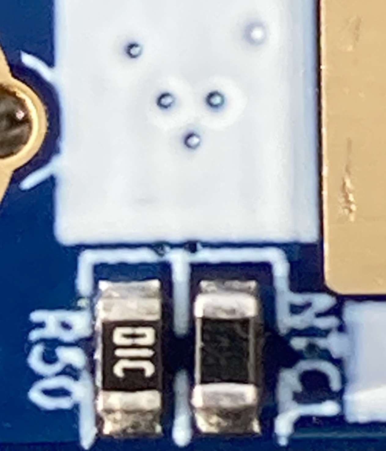
Image:Hall-Effect-Sensor01.jpg|Before install, location at U14 | Image:Hall-Effect-Sensor01.jpg|Before install, empty location at U14 | ||
Image:Hall-effect-sensor02.jpg|After install | Image:Hall-effect-sensor02.jpg|After install | ||
File:Hall-effect-sensor01.jpg| Only needs small amount of solder | |||
File:Hall-effect-sensor03.jpg| Kapton tape/protect the 3 Via holes above 3-pin side before soldering. | |||
File:NTC-temp-Sensor.jpg| Kapton tape/protect the NTC sensor on opposite side of V2 (V1 does not have this) | |||
</gallery> | </gallery> | ||
== Go back to Pinecil article == | == Go back to Pinecil article == | ||
Go back to [[Pinecil|Pinecil article]]. | Go back to [[Pinecil|Pinecil article]]. | ||
[[Category:Pinecil]] | [[Category:Pinecil]] | ||
Latest revision as of 22:13, 18 June 2023
Instructions to install a hall effect sensor (HES) on the Pinecil V1 and V2.
The Hall Effect Sensor (HES) is an optional end user installed sensor that activates to put Pinecil to sleep when it enters a holder or stand. This requires a neodymium magnet attached to the stand. The closer the HES in the Pinecil is to the magnet, the more likely the HES will activate to enter sleep mode. This adds a feature to Pinecil that is often seen in high end pro irons.
Tools and Supplies
- Order a Hall Effect Sensor (SI7210-B-00 here), also at Digikey and Mouser.
- Ordering 2-3 might be a good idea in case the first one is damaged during install (if all goes well, one could mail the extras to a friend or another Pine64 member in the community chat ;).
- Jeweler's magnifying glasses or magnifying lamp or a microscope is recommended as the SOT23 chip is very small.
- Borrow a second soldering iron (this is when 2x Pinecils is a good idea).
- Get some neodymium magnets, just two 8x2.7mm at 8:00PM and 12:00PM on the stand could be enough. Experimentation is needed. Start with just one small magnet and increase the number placed around the stand until 360° sleep is activated when the Pinecil hits the stand.
- Reference Schematics are here (search for U14).
Videos
- Easy trick to Open Pinecil.
- How to install Hall Sensor video.
Installation
- Updating to the newest firmware before installing is recommended, see the Firmware article. These instructions are for 2.18 or newer firmware.
- The HES is located at the very front of the Pinecil, where the cartridge enters, see pcb images here.
- Once it is soldered, cleaned, and assembled, check the sleep menu, a new hall sensitivity option appears.
- See this article on how to set up the sensitivity settings on the firmware menu (Ralim's IronOS).
- Once you change the Sleep menu > Hall sensitivity to what you like, then scroll back to the main screen in order for the setting to be saved and persist on reboot.
- Note: IronOS firmware does not flash a setting change until one scrolls out of the sub-menu back to the main screen. This is to reduce the total number of flashes done as several settings might be changed in one section (number of flashes is not unlimited; most users will not encounter the maximum allowed flashes on normal use over years).
Hints
- Try not to overheat the sensor while soldering as that could damage it and even cause a leg to fall off.
- This is a small SOT23 chip. Tacking one pin on the 2-pin side helps to hold it in place before soldering the rest of the sensor.
- It is recommended to solder this with an iron with a small tip instead of using hot air (depends on your experience with hot air). See photos below, use kapton tape to protect nearby components: the 3 via holes above the 3-pin side, and the NTC temperature sensor on the other side. If too much heat is applied, it could damage the pcb, and/or affect the I2C and cause screen corruption.
- Apply generous flux to the area. If lead solder is being used, it is recommended to remove some of the existing no-lead solder that is already on the U14 pads.
- After the HES is soldered, clean the area completely with 99% isopropyl alcohol (IPA) and a soft toothbrush or small paint brush and dry before assembly. Air/hair dryer could be used to blow out some of the wet IPA. Not cleaning it well enough could cause some I2C noise on the screen. Try to keep IPA/alcohol away from OLED screens.
- If the stand/holder is not metal, tape magnets near where the Pinecil enters the hole in the holder to test out good locations. Hot glue is another option.
- When closing the handle, inspect that the the seam line is fully snaped closed; avoid pressing the screen.
Images
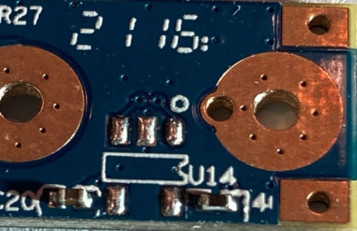
Before install, empty location at U14
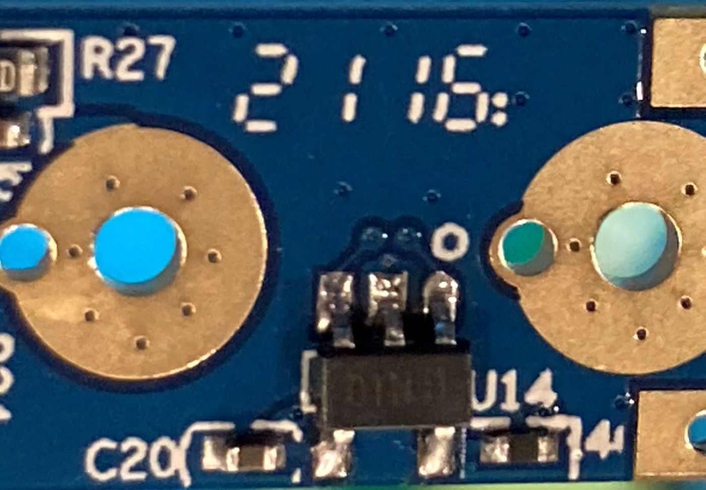
After install
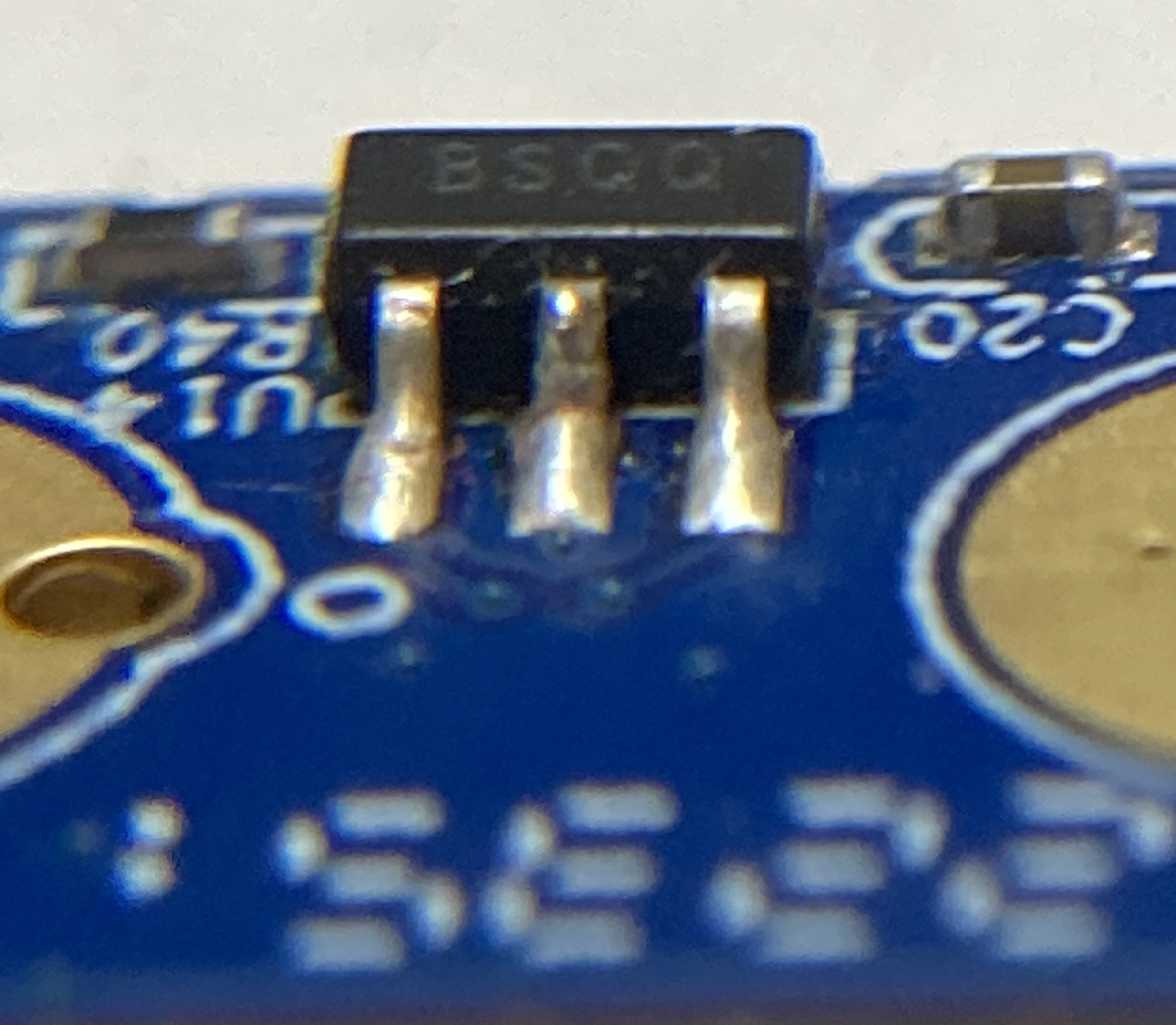
Only needs small amount of solder
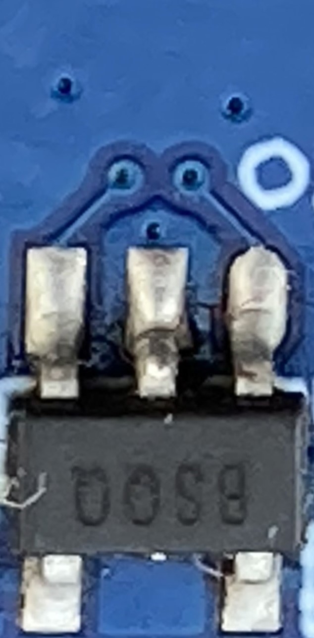
Kapton tape/protect the 3 Via holes above 3-pin side before soldering.
Kapton tape/protect the NTC sensor on opposite side of V2 (V1 does not have this)


Go back to Pinecil article
Go back to Pinecil article.