POT
Revision as of 02:55, 25 April 2016 by Pineadmin (talk | contribs) (→POT Board Recommended PCB Dimension)
Peripheral On Top (POT)
POT Board Recommended PCB Dimension
 POT board dimension for Pine A64 in DXF format
 POT board dimension for Pine A64 in PDF format
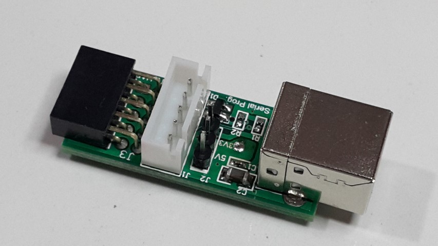
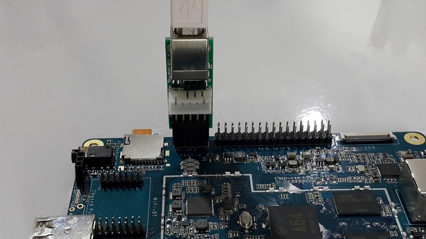
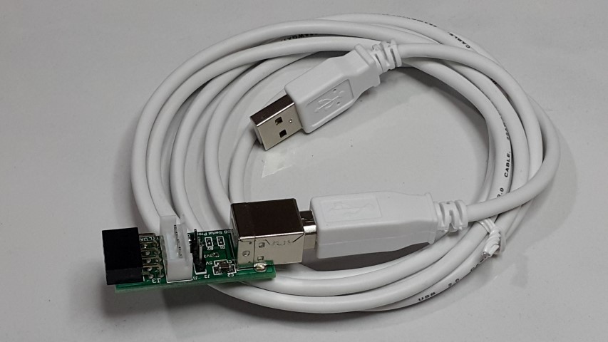
USB/UART Programming/Console Adapter (PMPROG01)
 Feature
 Base on Silicon Libs CP2102
 Support Virtual COM Port Device Drivers
 Support USBXpress™ Direct Driver Support
 With XH 5 pin 2.54mm pitch connector for UART connection
 Voltage Output on the connection is selectable to either 5V,3.3V or off
 On board USB-B Connector Receptor
 Connector J3 can direct insert into Pine A64 Exp-Bus to provide console access to Pine A64 board
 I/O pin are protected with ESD protector IC.
 On board 5x2pin connector can direct insert into Pine A64 Exp Bus for UART0 Console access
 Can use for programming and debugging for Wifi Remote I/O board

 Related Specification and Document
 [CP2102 Datasheet]
 [Virtual COM Port Driver]
 [USBXpress Driver]


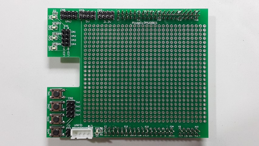
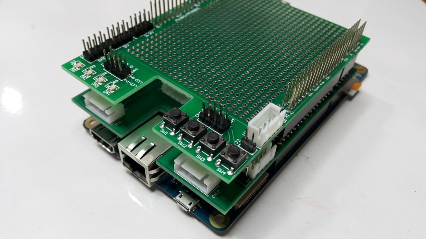
POT: Veroboard (PMVRB01)
Feature Sit on top of Pine A64 board All the header receptor will have extended length pin to allow other POT board to insert on top of it Allow easy access to all the I/O pin on the Pine A64 header On board 4pcs of LED with current limiting resistor all direct connect to I/O pin for status indicator On board 4pcs of Tact switch On board XH5 2.54mm pitch connector for UART0 allow easy connection to USB/UART adapter for console access
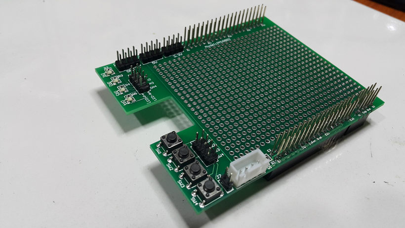
POT Veroboard on Pine A64
POT Veroboard 2 board stack on top of Pine A64


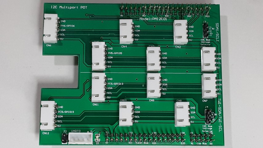
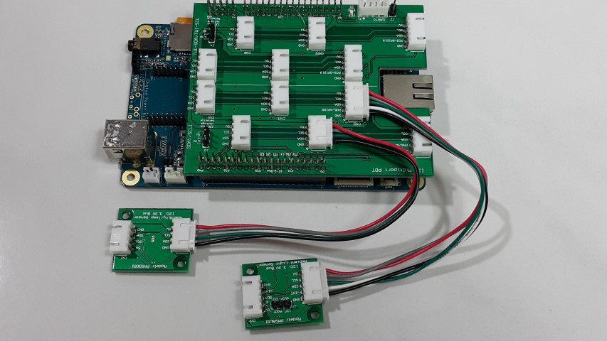
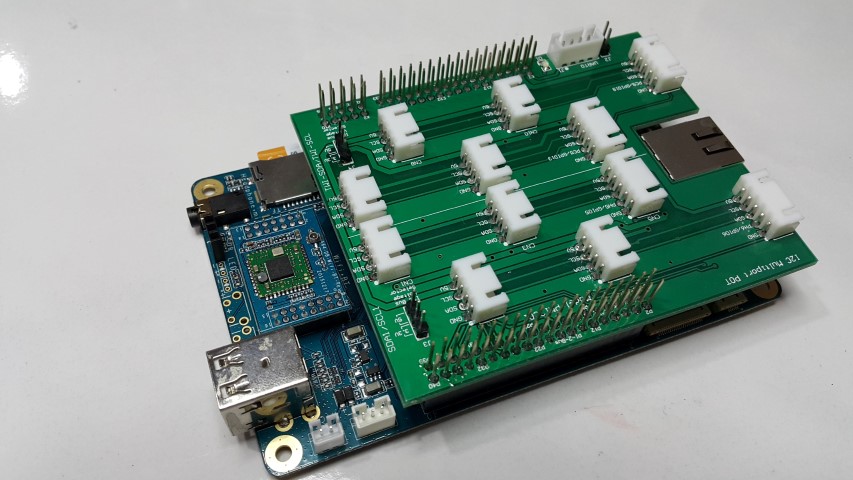
POT: Multi I2C Bus (PMI2C01)
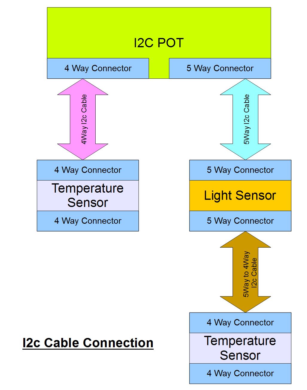
 Feature
 Sit on top of Pine A64 board
 All the header receptor will have extended length pin to allow other POT board to insert on top of it
 Allow easy access to all the I/O pin on the Pine A64 header
 2 channel of I2C bus is wire out for easy access
 I2C bus repeater IC (PCA9517A) are included in each I2C bus to allow connection of more devices on each bus
 Support 3.3V and 5V I2C bus for each channel separately
 On Board separated 3.3V supply regulator for 3.3V I2C Bus
 Each I2C bus pin are protected with ESD protector devices
 Each channel consist of 4 pcs of XH 4 pin 2.54mm pitch connector and 2 pcs of XH 5 pin 2.54mm pitch connector
 For the XH 4 pin connector, will consist of GND,SCL,SDA,5V pin
 For the XH 5 pin connector, will consist of GND,nINT,SCL,SDA,5V pin
 5V supplier is direct connect from Pine A64 adapter's supply thus prevent over loading Pine A64 board
 The nINT pin will allow peripheral with interrupt pin link back to the Pine A64 I/O pin

 Related Specification and Document
 NXP PCA9517A Datasheet
 NXP AN10658 Sending I2C-bus signal via long communication cables
 NXP AN11075 Driving I2C-bus signals over twisted pair cables with PCA9605


POT: Shield Adapter (PMARD01)
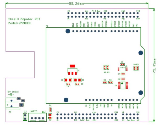
 Adapter for Arduino Shield
 Separate on board LM1117 3.3V LDO for the Shield
 Base on Maxim MAX11609 on ADC input. Allow up to 5V analog signal
 Extra 5V input DC jack socket (suitable for 4.0mm X 1.7mm DC Jack) for extra input power

 Related Specification and Document
 MAX11609 10bit I2C ADC


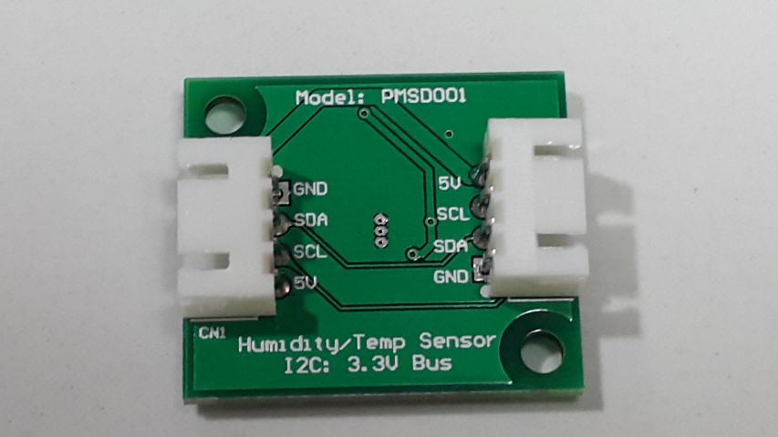
I2C Device: Humidity and Temperature Sensor (PMSDP01)
 Feature
 Base on Silicon Labs Si7021 I2C Humidity and Temperature Sensor
 High Accuracy Temperature Sensor ±0.4 °C (max), –10 to 85 °C
 0 to 100% RH operating range
 Up to –40 to +125 °C operating range
 On board 3.3V regulator
 2pcs of XH 4pin 2.54 mm pitch connector to allow daisy chain of multiple I2C sensor

 Related Specification and Document
 Si7021-A20 Datasheet


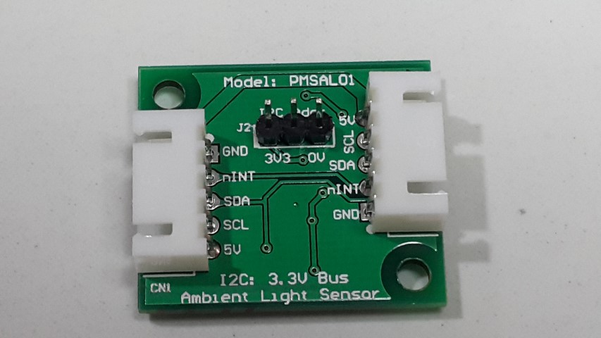
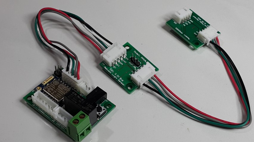
I2C Device: Ambient Light Sensor (PMSAL01)
 Feature
 Base on TAOS/AMS TSL2561T I2C Light Sensor
 Approximates Human Eye Response
 Programmable Interrupt Function allow user defined upper/lower limit trigger threshold
 Automatically rejects 50/60Hz lighting ripple
 Build with 2 channel of photodiode/ADC to allow more accurate calculation of light intensity (in Lux)
 Can support up to 3pcs of sensor in the same I2C channel
 On board 3.3V regulator
 2pcs of XH 5pin 2.54 mm pitch connector to allow daisy chain of multiple I2C sensor

 Related Specification and Document
 TSL2561T Datasheet


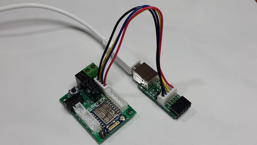
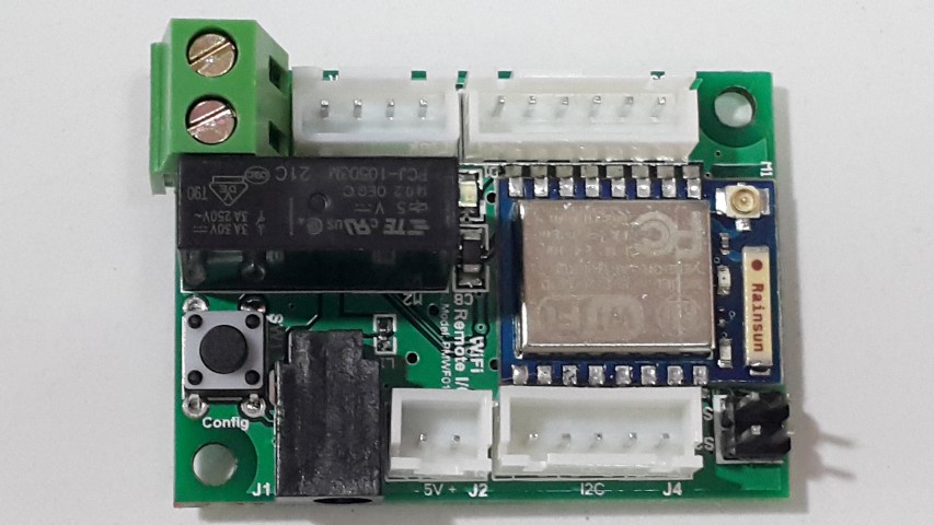
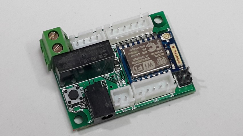
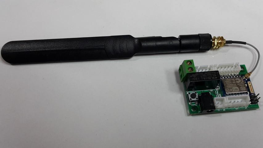
WiFi Remote I2C (PMWF01A)
 Feature
 Base on ESP8266 Wifi Chipset
 Connect to Wifi AP
 On board chip antenna or U-FL connector for external antenna
 On board relay contact (TE PCJ-105D3M with 3A 275Vac Contact) with screw type terminal contact to support AC Line On/Off
 On board 1pc Tact-switch
 XH 5 2.54mm pitch connector connecting I2C device
 XH 6 2.54mm pitch connector for GPIO/SPI/PWM output
 XH 2 2.54mm pitch connector for system power 5V input or output
 DC Jack socket (suitable for 4.0mm X 1.7mm DC Jack) for system power input
 UART Port connector ready for on chip programming using USB/UART Programming/Console Adapter (PMPROG01)
 2pcs of XH 5pin 2.54 mm pitch connector to allow daisy chain of multiple I2C sensor

 Related Specification and Document
 TE PCJ-105D3M Relay Datasheet
 ESP8266 Datasheet
 ESP8266 forum


Inter Connection Wire