SOEDGE
Jump to navigation
Jump to search
Software and OS Image Downloads
SOEdge_Software_Release
Accessories Step-by-Step Guides
Under 'Guides for model A baseboard accessories' you can find instructions and guides concerning:
- Enclosures
- Bluetooth and WiFi module
- Real Time Clock (RTC) battery
- Real Time Clock (RTC) battery holder
- First and third party cases
- Featured 3D printed cases (and more)
SoC and Memory Specification
- Based on Rockchip RK1808
CPU Architecture
- Dual-core ARM Cortex-A35 Processor@1600-2000Mhz
- A power-efficient ARM 64-Bit Armv8-A architecture
- AArch32 for full backward compatibility with Armv7
- Support NEON Advanced SIMD (Single Instruction Multiple Data) instruction for acceleration of media and signal processing function
- Support Large Physical Address Extensions(LPAE)
- VFPv4 Floating Point Unit
- 32KB L1 Instruction cache and 32KB L1 Data cache
- AArch64 for 64-bit support and new architectural features
- TrustZone security technology
- Neon Advanced SIMD
- DSP and SIMD extensions
- VFPv4 Floating point
- Hardware virtualization support
- 128KB L2 cache
Neural Process Unit NPU Capability
- NPU IP from Verisilicon Vivantee
- Support max 1920 Int8 MAC operation per cycle
- Support max192 Int16 MAC operation per cycle
- Support max 64 FP16 MAC operation per cycle
- 512KB internal buffer
- One isolated voltage domain to support DVFS
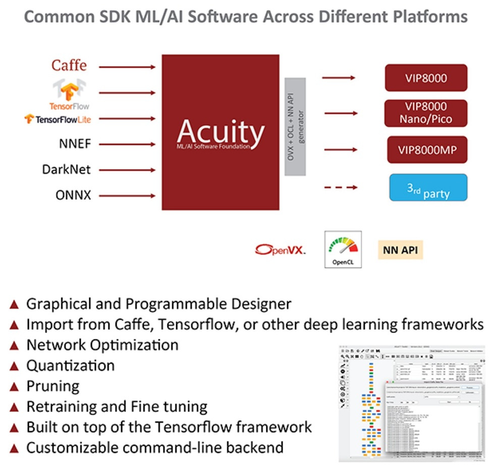
- Acuity models Github
System Memory
- RAM Memory Variants: 2GB DDR4.
- Storage Memory: SPI Flash and optional eMMC module from 16GB up to 128GB
SOEdge Baseboard Features
Network
- 10/100/1000Mbps Etherne
- WiFi 802.11 b/g/n with Bluetooth 4.0 (optional)
Storage
- microSD - bootable, support SDHC and SDXC, storage up to 256GB
- USB - 2 USB2.0 Host port
Expansion Ports
- DSI - Display Serial Interface, 4 lanes MiPi, up to 1080P
- CSI - CMOS Camera Interface up to 5 mega pixel
- TP - Touch Panel Port, SPI with interrupt
- RTC - Real Time Clock Battery Connector
- VBAT - Lithium Battery Connector with temperature sensor input
- Wifi/BT Module Header - SDIO 3.0 and UART
- 2x20 pins "Pi2" GPIO Header
- PCIe 2x open ended slot
SOEdge Module and Baseboard Information, Schematics, and Certifications
- Model "A" Baseboard Dimensions: 133mm x 80mm x 19mm
- Input Power: DC 12V @ 3A 5.5OD/2.1ID Barrel DC Jack connector
- SOEdge Module Schematic:
- SOEdge Module ver 2.0 20190919 Schematic
- SOEdge Module ver 2.0 20190919 PCB Component Placement Top PDF file
- SOEdge Module ver 2.0 20190919 PCB Component Placement Bottom PDF file
- SOEdge Module ver 2.0 20190919 PCB Component Placement Top Drawing file
- SOEdge Module ver 2.0 20190919 PCB Component Placement Bottom Drawing file
- SOEdge Module Pin Assignment ver 1.0 in Excel format(includes comparison chart to SOPine)
- SOEdge Module Pin Assignment ver 1.0 in Open Document format(includes comparison chart to SOPine)
- SOEdge Model "A" Baseboard Schematic and PCB Board Resource:
- SOEdge Neural AI Stick Schematic:
- SOEdge/SOPine/PINE A64 Wifi/BT module Schematic
- SOEdge module together with model "A" baseboard Certification:
- Disclaimer: Please note that SOEdge module is not a "final" product and in general certification is not necessary. However, SOEdge module still submits the mpdel A baseboard for FCC, CE, and ROHS certifications and obtain the certificates to prove that can pass the testing. Please note, a final commercial product needs to perform its own testing and obtain its own certificate.
- Not yet available
Datasheets for Components and Peripherals
- Rockchip RK1808 SoC information:
- Rockchip RK809 PMU (Power Management Unit) information:
- DDR4 information:
- eMMC information:
- SPI NOR Flash information:
- SOEdge Related:
- 5MPixel CMOS Camera module information:
- LCD Touch Screen Panel information:
- Ethernet PHY information:
- Wifi/BT module information:
- Enclosure information:
- Connector information:
SOEdge/SOPine Cluster Board Resource
- Cluster board is an hardware open source project and will be available at PINE64 store on late January 2018.
- Please note that this project is not "OSH" compliance.:
- Clusterboard version 2.2 Schematic Capture source file
- Clusterboard version 2.2 Schematic Capture PDF file
- Clusterboard version 2.2 PCB Job source file
- Clusterboard version 2.2 PCB Gerber file
- Clusterboard version 2.2 PCB Layout PDF file
- Clusterboard 20pins header definition
- Clusterboard 3D drawing in Fusion360
- Clusterboard PDF drawing

