PineTime Devkit Wiring
This article will help you get up to scratch about how to connect your PineTime to your hardware debugger and what to keep in mind.
The devkit comes with a set of wires you can use for connecting your programmer to the SWD pins. Most people use friction to make contact with the programming cable. Soldering the wires to the pinetime is not recommended, especially if you don't have a temperature-controlled iron and good confidence that you can do it - the thin PCB is fragile and easy to break.
Current amount of dead PineTimes (or ruined bundled programming connectors) due to attempted soldering is 5 (update this number when suitable).
Read this about the battery:
You have three choices:
a) If you have a soldering iron and you're confident with using it, it is recommended that you remove the battery until you actually need it. Doing so avoids unnecessary charge cycles and strain on it. It can also potentially prevent issues with your watch not resetting properly or backfeeding power into your debugger-programmer. There's also the option that you just connect a microswitch between the battery's positive side and the PineTime, just make sure to isolate your connections so it doesn't short out against anything.
b) If you do not have a soldering iron or you're not confident with using it, don't disconnect the battery if you ever plan on using it. Don't bend the wires too much as they're thin, you won't be able to reconnect it. Keep in mind that keeping it connected during development will probably reduce the lifetime of the battery. Small load on the 3.3V pin is probably fine, but it will drain the battery empty. Having the battery connected when it's not empty will also very likely backfeed power into your 3.3V pin - don't cause short circuits! don't leave the wire dangling!
c) If you don't disconnect the battery, also don't connect the 3.3V pin from the SWD cable when debugging or updating firmware. You only need to use the GND, SWDIO and SWDCLK pins. In that case the watch will run exclusively on battery, but there is no danger of backfeeding power.
SWD Pinout
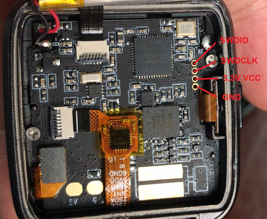
The devkits have exposed SWD pins for flashing and debugging.
The pinout is:
Pogo Pins connection
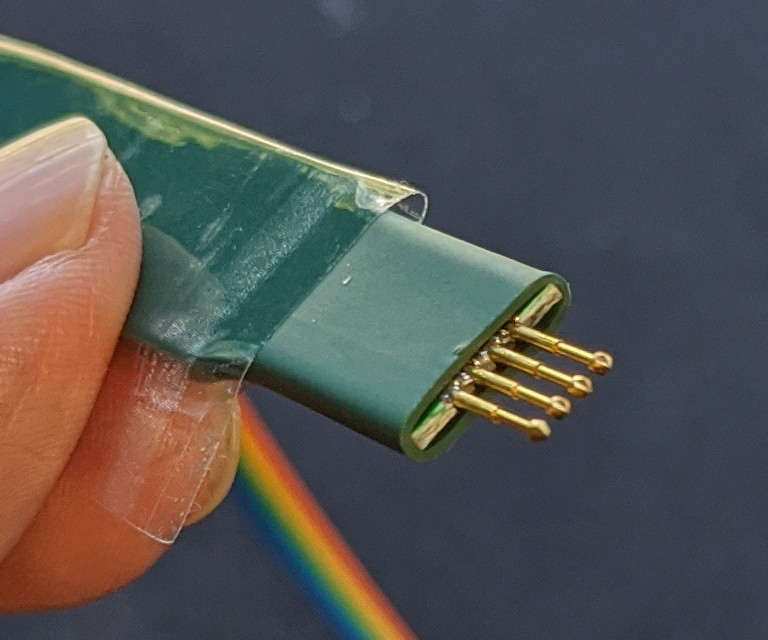
PineTime Pogo Pins are spring-loaded pins with diamond-shaped tips...
The Pogo Pins are meant to be connected temporarily to PineTime's SWD port for firmware flashing and simple firmware debugging...
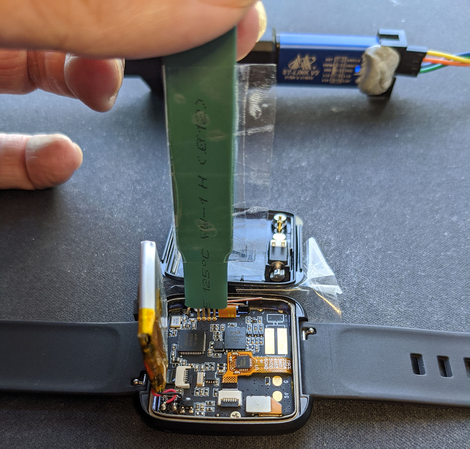
The other end of the Pogo Pins connects to ST-Link v2 or JLink for flashing and debugging. (ST-Link v2 is shown in the background)
To connect PineTime Pogo Pins to PineTime's SWD Port:
- To orientate the pins, stick a piece of Sticky Tape to the Pogo Pins as shown above. The Sticky Tape should point away from PineTime's Battery. Orientation is important... You may damage PineTime with the incorrect orientation!
- With the Battery at left and Sticky Tape pointing right, the SWD Pins will be arranged left to right as: SWDIO, SWDCLK, 3.3V, GND
- Connect the other end of the Pogo Pins to the Jumper Cable that's bundled with PineTime. Connect the Jumper Cable to ST-Link v2 or JLink: SWDIO, SWDCLK, 3.3V, GND. See Reprogramming the PineTime
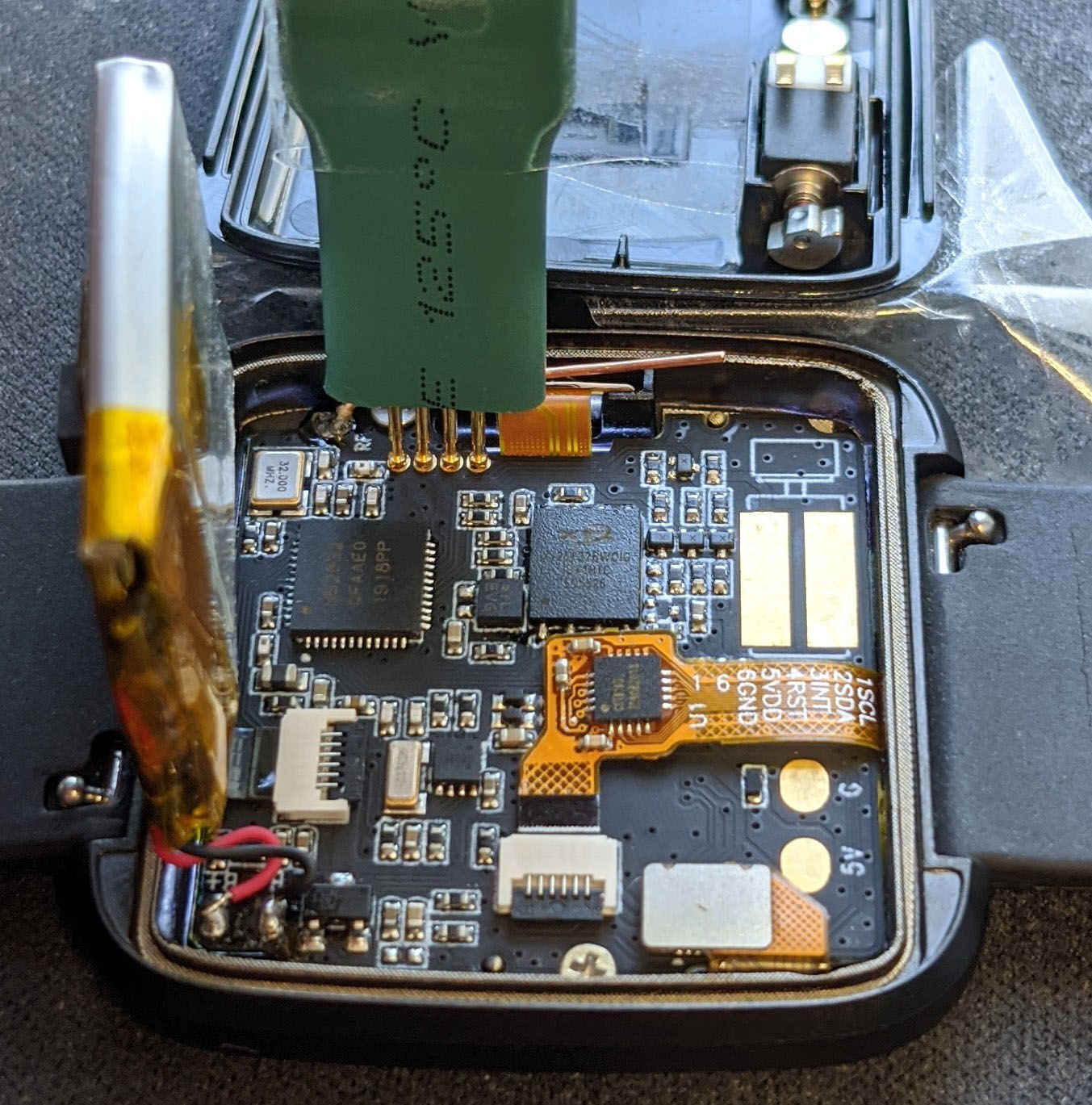
- With the Sticky Tape pointing right (away from the Battery), tap and hold the Pogo Pins firmly on PineTime's SWD Port... But not too hard because the PCB or screen may break. Stabilise the Pogo Pins with your pinky finger as shown above.
- PineTime should light up and reboot when the Pogo Pins are connected. You may flash and debug PineTime now. See Reprogramming the PineTime
The tips of the Pogo Pins will partially penetrate the SWD holes like this... (Don't force them in!)
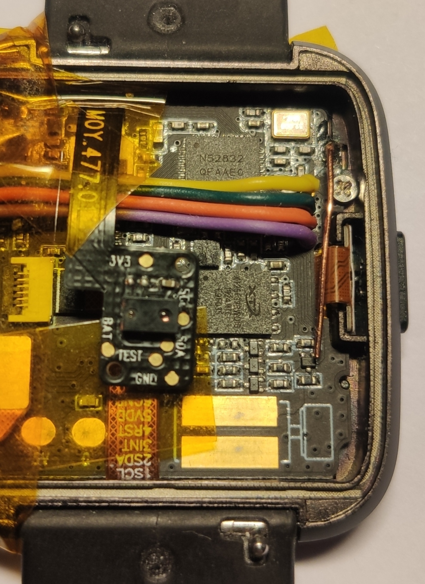
Soldered wires example
Before attempting this, make sure you have a good soldering iron, some magnification and you haven't set your iron too high. If you haven't ever before soldered things this small, you really really do not want to start out on something this dense, small and thus fragile.
Raspberry Pi connection
See PineTime Updater
