Pinebook Pro
User Guide
Introducing PineBook Pro
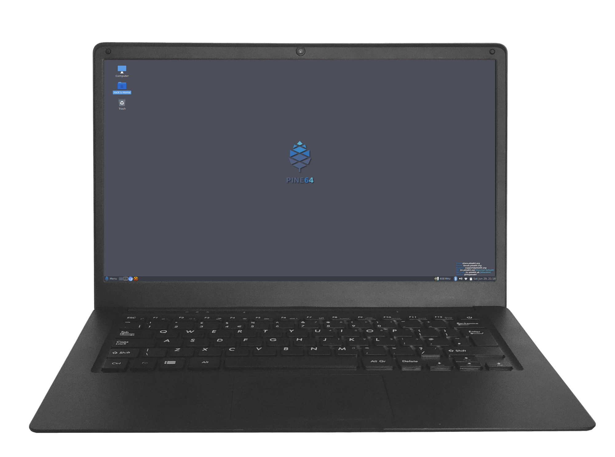
The Pinebook Pro is a Linux and *BSD ARM laptop from PINE64
It is built to be a compelling alternative to mid-ranged Chromebooks that people convert into Linux laptops. It features an IPS 1080p 14″ LCD panel, a premium magnesium alloy shell, high capacity eMMC storage, a 10,000 mAh capacity battery, and the modularity that only an open source project can deliver.
Key features include: the RK3399 SOC; USB-C for data, video-out and power-in (3A 5V); privacy switches for the microphone, BT/WiFi module, and camera; and expandable storage via NVMe (PCIe 4x) with an optional adapter.
The Pinebook Pro is equipped with 4GB LPDDR4 system memory, high capacity eMMC flash storage, and 128Mb SPI boot Flash. The I/O includes: 1x micro SD card reader (bootable), 1x USB 2.0, 1x USB 3.0, 1x USB type C Host with DP 1.2 and power-in, PCIe 4x for an NVMe SSD drive (requires an optional adapter), and UART (via the headphone jack by setting an internal switch).
The keyboard and trackpad both use the USB 2.0 protocol. The LCD panel uses eDP MiPi display protocol.
Many different Operating Systems (OS) are freely available from the open source community and partner projects. These include various flavors of Linux (Ubuntu, Debian, Manjaro, etc.) and *BSD.
Software and OS Image Downloads
Pinebook Pro
Under 'Pinebook Pro Software and OS Image Download Section' you will find a complete list of currently supported Operating System images that work with the Pinebook as well as other related software.
The list includes OS images and descriptions of:
 Debian Desktop (microSD and eMMC Boot)
 Bionic LXDE (microSD and eMMC Boot)
 Bionic Mate (microSD and eMMC Boot)
 Chromium (microSD and eMMC Boot)
 Android 7.1 (microSD Boot)
  Android 7.1 (eMMC)
Quick Links to OS Images Build Sources
Some of the provided OS images are still in beta or nightly build and only fit for testing purposes. These images ought to be avoided for normal usage - use them at your own risk
- ayufan's Linux build repo
- ayufan's Chromium OS build repo
- mrfixit2001's Linux debian desktop build repo
Keyboard
The Pinebook Pro is available in two keyboard configurations: ISO and ANSI. Both the keyboard and trackpad in the Pinebook Pro use the USB 2.0 protocol and show up as such in xinput. The keyboard features function (Fn) keys in the F-key row, which include display brightness controls, sound volume, trackpad lock, and other functionality. There is also a custom PINE64 logo key that functions as Menu/Super key. It has also a secondary functionality for setting the privacy switches.
The keyboard firmware is open sourced can be flashed from userspace using the provided utility.
Documentation for the keyboard can be found in Datasheets for Components and Peripherals.
German umlaute and the like
On the UK Layout you can type umlaute by pressing [AltGr]+["] followed by [A], [O], [U], [a], [o] or [u]. The key combination [AltGr]+[s] generates the letter 'ß'.
Privacy Switches
There are three privacy switches mapped to the F10, F11 and F12 keys on the Pinebook Pro keyboard. They de/activate the following:
| Combination | Effect | Description |
|---|---|---|
| PINE64 logo key+F10 | Microphone Privacy switch | CAPs lock LED blinks. 2 blinks = enabled, 3 blinks = disabled |
| PINE64 logo key+F11 | WiFi Privacy switch | NUM lock LED blinks. 2 blinks = enabled, 3 blinks = disabled. Re-enabling requires reboot. |
| PINE64 logo key+F12 | Camera privacy switch | CAPs lock and NUM lock LEDs blink together. 2 blinks = enabled, 3 blinks = disabled |
(Press the PINE64 logo key plus Fn (10/11/12) for 3 seconds)
The keyboard uses special firmware that operates separately of the operating system. It detects if either the F10, F11 or F12 key, and the Pine key were pressed for 3 seconds. This disables the peripherals as listed above by cutting off their power. Which has the same result as cutting off the power to each peripheral with a physical switch. This implementation is very secure since the firmware that determines whether a peripheral gets power is not a part of the Pinebook Pro’s operating system. So the power state value for each peripheral cannot be overridden or accessed from the operating system. The power state setting for each peripheral is stored across reboots.
Trackpad
The trackpad is large, smooth (metallic to-the-touch), and has two actuating buttons. It is the only component of the Pinebook Pro held in place with strong adhesive tape. It supports multi-touch functionality.
The trackpad firmware is open sourced and can be flashed from userspace using the provided utility (https://github.com/ayufan-rock64/pinebook-pro-keyboard-updater[1]). However, the firmware shipped with the provided utility (as of 11/07/2019) can result in a bricked trackpad and thus should not be used until a revised version of said firmware has been published to the linked repo.
Documentation trackpad can be found in Datasheets for Components and Peripherals.
Power Supply
Input Power: DC 5V @ 3A 3.5mm OD/ 1.35mm ID Barrel jack or USB-C 15W PD quickcharge
LEDs
In total there are four LEDs on the Pinebook Pro, three of which are placed in the top left side of the keyboard, and one near the barrel-port:
- 1. The red LED next to the barrel-port indicates charging. It will illuminate when mains power is supplied to the Pinebook Pro from either the standard power supply unit or a USB-C smartphone charger.
- 2. The power indicator LED on the Pinebook Pro supports three different colours: green, amber and red. It is also capable of flashing/blinking to indicate activity. In the default Debian with MATE build, green LED means power and red means suspend (amber is unused).
- 3. The Num lock, green LED.
- 4. The Caps lock, green LED.
(The Num and Caps lock LEDs have a secondary function. When the privacy switches get activated they blink to confirm that switch has been activated.)
Webcam
WIP
Microphones
WIP
Bluetooth and WiFi
WIP
LCD Panel
WIP
Using UART
UART output is enabled by flipping the UART switch to on position (item 9). To do so you need to remove the Pinebook Pro's bottom cover - please follow proper disassembly and reassembly protocol. The OFF position is towards the touchpad, the ON position is towards the display hinges.
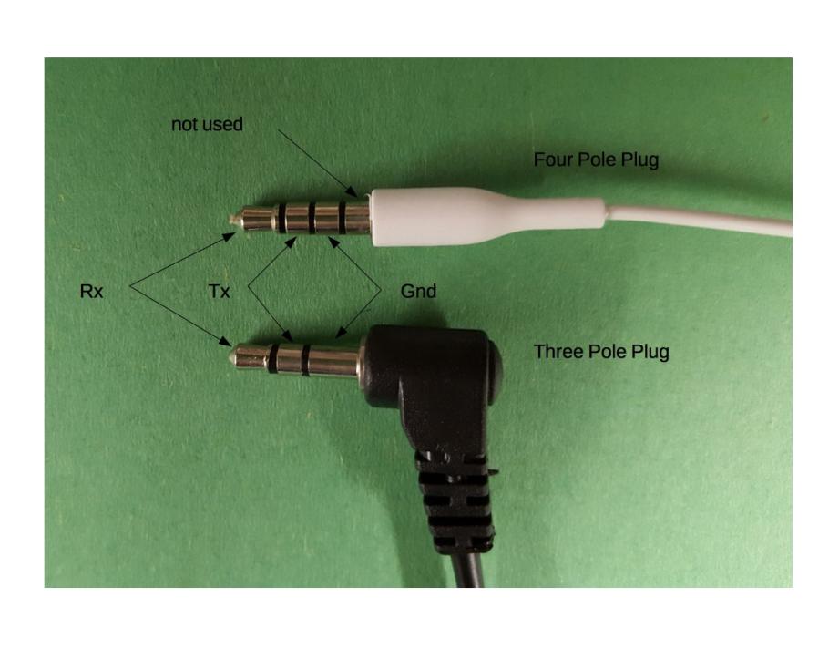
With the UART switch in the 'on' position, console is relayed via the audiojack and the laptop's sound is turned off. PINE64 store sells a dedicated serial console but you can make your own if you have a serial console USB 2.0 adapter and old/ broken headphones.
Insert the USB plug of the cable into an open USB port on the machine which will monitor. Run the following in a terminal:
$ lsusb
you should find a line similar to this:
Bus 001 Device 058: ID 1a86:7523 QinHeng Electronics HL-340 USB-Serial adapter
You may have to clean the USB contacts of the Serial cable to get a good connection if you do not find that line.
The audio jack of the Serial cable should be fully inserted into the Pinebook Pro audio port.
Serial output should now be accessible using screen, picocom or minicom (and others). Examples:
screen /dev/ttyUSB0 1500000
picocom /dev/ttyUSB0 -b 1500000
minicom -D /dev/ttyUSB0 -b 1500000
Using the PineBook Pro
Bypass Cables
The mainboard features two (disconnected by default) bypass cables that are only to be used with the battery disconnected. The female (10) male (6) ends of the bypass cables can be connected to provide power to the mainboard if you need to run the laptop without a battery. Please refer to this engineering notice.
WARNING: Do not connect the bypass cables with the battery connected. Using the bypass cables with the battery connected can permanently damage the computer.
Pinebook Service Step-by-Step Guides
Placeholder for Pinebook Pro specific guides
Under 'Service Guides for Pinebook' you can find instructions guides concerning disassembly of:
Note: The installation process on Pinebook Pro similar to 14" Pinebook
Note: The installation process is the reverse order of removal guide
- 14″ Pinebook Lithium Battery Pack Removal Guide
- 14″ Pinebook LCD Panel Screen Removal Guide
- 14″ Pinebook eMMC Module Removal Guide
Technical Reference
Accessing the Internals - Disassembly and Reassembly
WARNING: Do not open the laptop by lifting the lid while the Pinebook Pro bottom cover is removed - this can cause structural damage to the hinges and/or other plastic components of the chassis such as the IO port cut-outs.
WARNING: When removing the back cover plate, use care if sliding fingertips between back cover plate and palm rest assembly. The back cover plate edges are sharp.
When disassembling the laptop make sure that it is powered off and folded closed. To remove the bottom cover of the Pinebook Pro, first remove the ten (10) Phillips head screws that hold the bottom section of the laptop in place. Remove the cover from the back where the hinges are situated by lifting it up and away from the rest of the chassis.
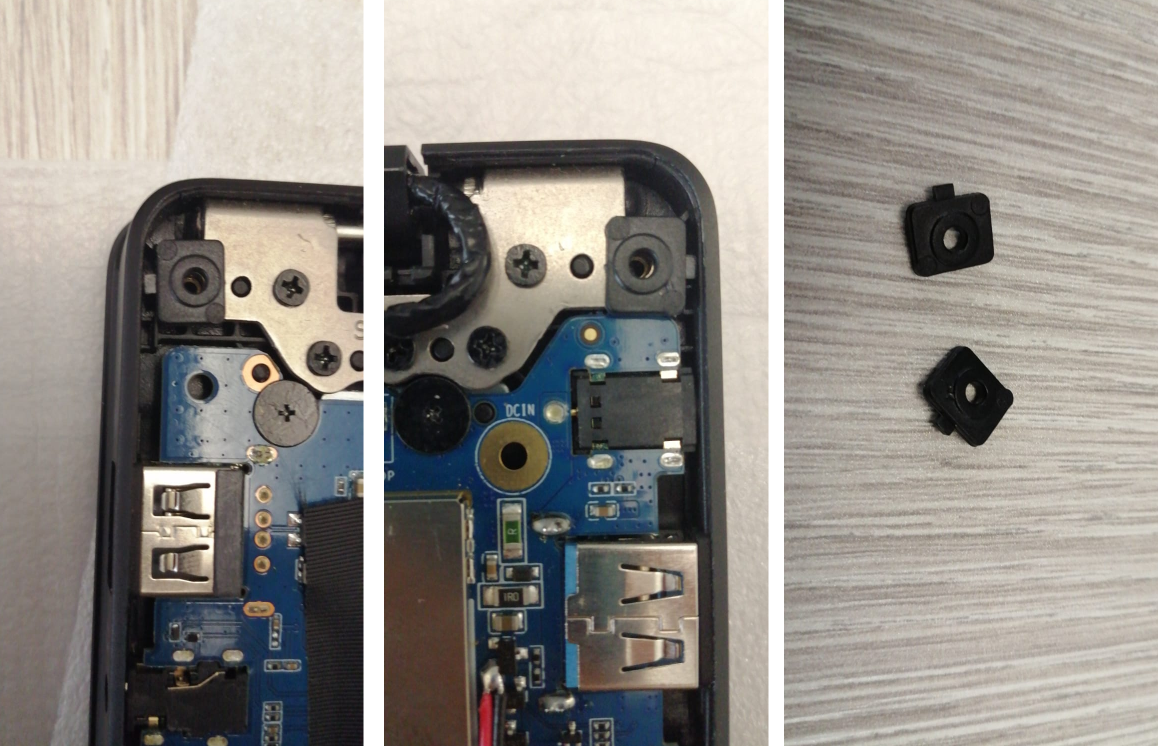
During reassembly, make sure that the back-screw standoffs are in place and seated correctly. To reassemble the Pinebook Pro, slide the bottom section into place so it meets the front lip of the keyboard section. Secure the front section (where the trackpad is located) in place using the short screws in the front left and right corners. Then proceed to pop in the bottom panel into place. Secure the bottom section (where hinges are located) by screwing in the left and right corners. Then screw in the remaining screws and run your finger though the rim on the chassis to make sure its fitted correctly. Note that the front uses the remaining 2 short screws.
NOTE: The screws are small and should only be finger tight. Too much force will strip the threads. If after installing screws the back cover plate has not seated properly on one side, open the display and hold the base on either side of the keyboard and gently flex the base with both hands in opposing directions. Once the side pops further in, then recheck the screws on that side. If it does not pop back in, just let it be.
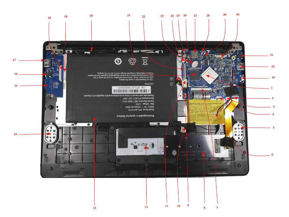
Pinebook Pro Internal Layout
Main chips
- RK3399 system-on-chip (1)
- LPDDR4 SDRAM (21)
- SPI NOR flash memory (29)
- eMMC flash memory (26)
- WiFi/BT module (27)
Mainboard Switches and Buttons
There are two switches on the main board: disabling the eMMC (24), and enabling UART (9) via headphone jack.
The Reset and Recovery buttons (28): the reset button performs an immediate reset of the laptop. The Recovery button is used to place the device in maskrom mode; this mode allows flashing eMMC using Rockchip tools (e.g. rkflashtools).
Key Internal Parts
| Number | Type | Descriptor |
|---|---|---|
| 1 | Component | RK3399 System-On-Chip |
| 2 | Socket | PCIe 4X socket for optional NVMe adapter |
| 3 | Socket | Speakers socket |
| 4 | Socket | Trackpad socket |
| 5 | Component | Left speaker |
| 6 | Connector | Male power bridge connector |
| 7 | Socket | Keyboard Socket |
| 8 | Component | Optional NVMe SSD adapter |
| 9 | Switch | UART/Audio switch - outputs UART via headphone jack |
| 10 | Socket | Female power bridge socket |
| 11 | Socket | Battery socket |
| 12 | Component | Trackpad |
| 13 | Component | Battery |
| 14 | Component | Right speaker |
| 15 | Socket | Micro SD socket |
| 16 | Socket | Headphone / UART jack |
| 17 | Socket | USB 2.0 |
| 18 | Socket | Daughterboard-to-mainboard ribbon cable socket |
| 19 | Cable | Daughterboard-to-mainboard ribbon cable |
| 20 | Component | microphone |
| 21 | Component | LPDDR4 RAM |
| 22 | Socket | Mainboard-to-daughterboard ribbon cable socket |
| 22 | Socket | Mainboard-to-daughterboard ribbon cable socket |
| 23 | Socket | Microphone socket |
| 24 | Switch | Switch to hardware disable eMMC |
| 25 | Antenna | BT/WiFI antenna |
| 26 | Component | eMMC flash memory module |
| 27 | Component | BT/WiFi module chip |
| 28 | Buttons | Reset and recovery buttons |
| 29 | Component | SPI flash storage |
| 30 | Socket | eDP LCD socket |
| 31 | Socket | Power in barrel socket |
| 32 | Socket | USB 3.0 |
| 33 | Socket | USB type C |
Bootable Storage
The Pinebook Pro is capable of booting from eMMC, USB 2.0, USB 3.0, or an SD card. It cannot boot from USB-C. The boot order of the hard-coded ROM of its RK3399 SoC is: SPI NOR, eMMC, SD, USB OTG.
At this time, the Pinebook Pro ships with a Debian + MATE build with uboot on the eMMC. Its boot order is: SD, then eMMC. Booting off USB storage is not currently available, but will be in the future.
(An update has been pushed for the default Debian + MATE build that improves compatibility with booting other OSs from an SD card. In order to update, fully charge the battery, establish an internet connection, click the update icon in the toolbar, and then reboot your Pinebook Pro. Please see this log for details.)
Please note that PCIe, the interface used for NVMe SSD on the Pinebook Pro, is not bootable on the RK3399 and therefore is not a part of the boot hierarchy. It is possible to run the desired OS from NVMe by pointing extlinux on the eMMC to rootfs on the SSD. This requires uboot, the Kernel image, DTB, and extlinux.conf in a /boot partition on the eMMC.
eMMC information
The eMMC storage will show up as multiple block devices:
- mmcblk1boot0 - eMMC standard boot0 partition, may be 4MB
- mmcblk1boot1 - eMMC standard boot1 partition, may be 4MB
- mmcblk1rpmb - eMMC standard secure data partition. may be 16MB
- mmcblk1 - This block contains the user areas
Only the last is usable as regular storage device in the Pinebook Pro. The device number of "1" shown above may vary, depending on kernel.
Boot sequence details
The RK3399's mask 32KB ROM boot code looks for the next stage of code at byte off-set 32768. This is where u-Boot code would reside on any media that is bootable.
Pinebook Pro Dimensions
- Dimensions: 329mm x 220mm x 12mm (WxDxH)
- Weight: 1.26Kg
SoC and Memory Specification
- Based on Rockchip RK3399
CPU Architecture
- big.LITTLE architecture: Dual Cortex-A72 + Quad Cortex-A53, 64-bit CPU
- Full implementation of the ARM architecture v8-A instruction set (both AArch64 and AArch32)
- ARM Neon Advanced SIMD (single instruction, multiple data) support for accelerated media and signal processing computation
- ARMv8 Cryptography Extensions
- VFPv4 floating point unit supporting single and double-precision operations
- Hardware virtualization support
- TrustZone technology support
- Full CoreSight debug solution
- One isolated voltage domain to support DVFS
- Cortex-A72 (big cluster):
- Dual-core Cortex-A72 up to 2.0GHz CPU
- Superscalar, variable-length, out-of-order pipeline
- L1 cache 48KB Icache and 32KB Dcache for each A72
- L2 cache 1024KB for big cluster
- Cortex-A53 (little cluster):
- Quad-core Cortex-A53 up to 1.5GHz CPU
- In-order pipeline with symmetric dual-issue of most instructions
- L1 cache 32KB Icache and 32KB Dcache for each A53
- L2 cache 512KB for little cluster
- Cortex-M0 (control processors):
- Two Cortex-M0 cooperate with the central processors
- Thumb instruction set
- 32 bit only
GPU Architecture
- ARM Mali-T860MP4 Quad-core GPU
- The highest performance GPUs built on Arm Mali’s famous Midgard architecture, the Mali-T860 GPU is designed for complex graphics use cases and provide stunning visuals for UHD content.
- Frequency 650MHz
- Throughput 1300Mtri/s, 10.4Gpix/s
- OpenGL® ES 1.1, 1.2, 2.0, 3.1, 3.2., Vulkan 1.0*., OpenCL™ 1.1, 1.2., DirectX® 11 FL11_1., RenderScript™.
System Memory
- RAM Memory:
- LPDDR4
- Dual memory channels on the CPU, each 32 bits wide
- Quad memory channels on the RAM chip, each 16 bits wide, 2 bonded together for each CPU channel
- 4GB as a single 366 pin mobile RAM chip
- Storage Memory:
- 64GB eMMC module, can be upgraded to a 128GB eMMC module. (The initial PINE64 community build version shipped with a 128GB eMMC.)
Battery
- Lithium Polymer Battery (10,000 mAH)
Display
- 14.1" 1920x1080 IPS LCD panel
Video out
- USB-C Alt mode DP up to 3840x2160 p60
Audio
- 3.5mm stereo earphone/microphone plug
- Build in stereo speakers
Network
- WiFi 802.11 b/g/n/ac with Bluetooth 5.0
Expansion Ports
- MicroSD card:
- Bootable
- Supports SD, SDHC and SDXC cards, up to 256GB
- Version SD3.0, up to 50MB/s
- USB ports:
- 1 x USB 2.0 Type-A Host Port, bootable
- 1 x USB 3.0 Type-A Host Port, 5Gbps, is not bootable
- 1 x USB 3.0 Type-C OTG Port, 5Gbps, (includes laptop charging function), is not bootable
- Headphone jack switchable to UART console mux circuit
- Optional NVMe adapter:
- PCIe 2.x, 5GT/s per lane
- 4 PCIe lanes, can not be bifurcated
- Maximum length for M.2 card is 80mm (M.2 2280)
- Power: 2.5W continuous, 8.25W peak momentary
- Does not support SATA M.2 cards
- Does not support USB M.2 cards
Pinebook Pro Schematics and Certifications
- Pinebook Pro Main Board Schematic And Silkscreen:
- Pinebook Daughter Board Schematic:
- Pinebook Pro NVMe Adapter Schematic:
- Serial Console Earphone Jack Pinout:
- Pinebook Pro Certifications:
- Not Yet Available
Datasheets for Components and Peripherals
- Rockchip RK3399 SoC information:
- LPDDR4 (366 Balls) SDRAM:
- eMMC information:
- SPI NOR Flash information:
- Wireless related info:
- Audio Codec (ES8316)
- LCD Panel:
- Touchpad information:
- Keyboard information:
- Not Yet Available
- Full HD Camera sensor:
- Lithium Battery information:
Troubleshooting guide
Tips, tricks and other information for troubleshooting your Pinebook Pro
New from the factory - Pinebook Pro won't boot / power on
- Some Pinebook Pros came from the factory with the eMMC switch in the disabled position. It should be switched towards the back / hinge to enable the eMMC.
- The eMMC may have come loose during shipment. Open the back and verify that the eMMC is firmly seated.
- You may want to try unplugging the SD card daughterboard ribbon cable and see if it powers on (remove the battery and peel off a bit of the tape before unplugging it to avoid damage). If it does, try reseating it on both sides. It might have come loose during shipping.
- It's possible that your eMMC is empty from the factory. Simply create a bootable SD card and see if your Pinebook Pro boots. If so, you can then write an OS image to the eMMC.
Pinebook Pro won't boot when using UART console cable
- If you're using the UART cable sold on the Pine Store, you may want to see if it boots after you disconnect it. Some users report that custom-made cables based on FTDI UART adapters do not cause this issue.
Pinebook Pro will not power on after toggling the eMMC enable/disable switch
- This may happen if you meant to toggle the UART/Headphone switch (9) towards touchpad for headphone use and instead you toggled the eMMC enable/disable switch (24).
- After reenabling eMMC by toggling switch (24) towards hinge, if Pinebook Pro does not turn on then press the RESET button (28). It is clearly marked 'reset' on the PCB board.
Keys not registering / missing keys when typing
This issue occurs when your thumb or edge of the palm makes contact with left or right tip of the trackpad when you type. This is due to the palm rejection firmware being too forceful. Instead of only disabling the trackpad, so your cursor does not move all over the screen, it disables both the trackpad and the keyboard.
Using Fn+F7 to disable the touchpad will keep it from also disabling the keyboard.
A firmware update is planned to address this.


