Pinecil
Overall description
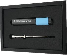
The Pinecil is a portable, temperature controlled soldering iron. It also has the intended use of being a Risc-V development device using a breakout board. It's main features are:
- Portability
- Settable temperature
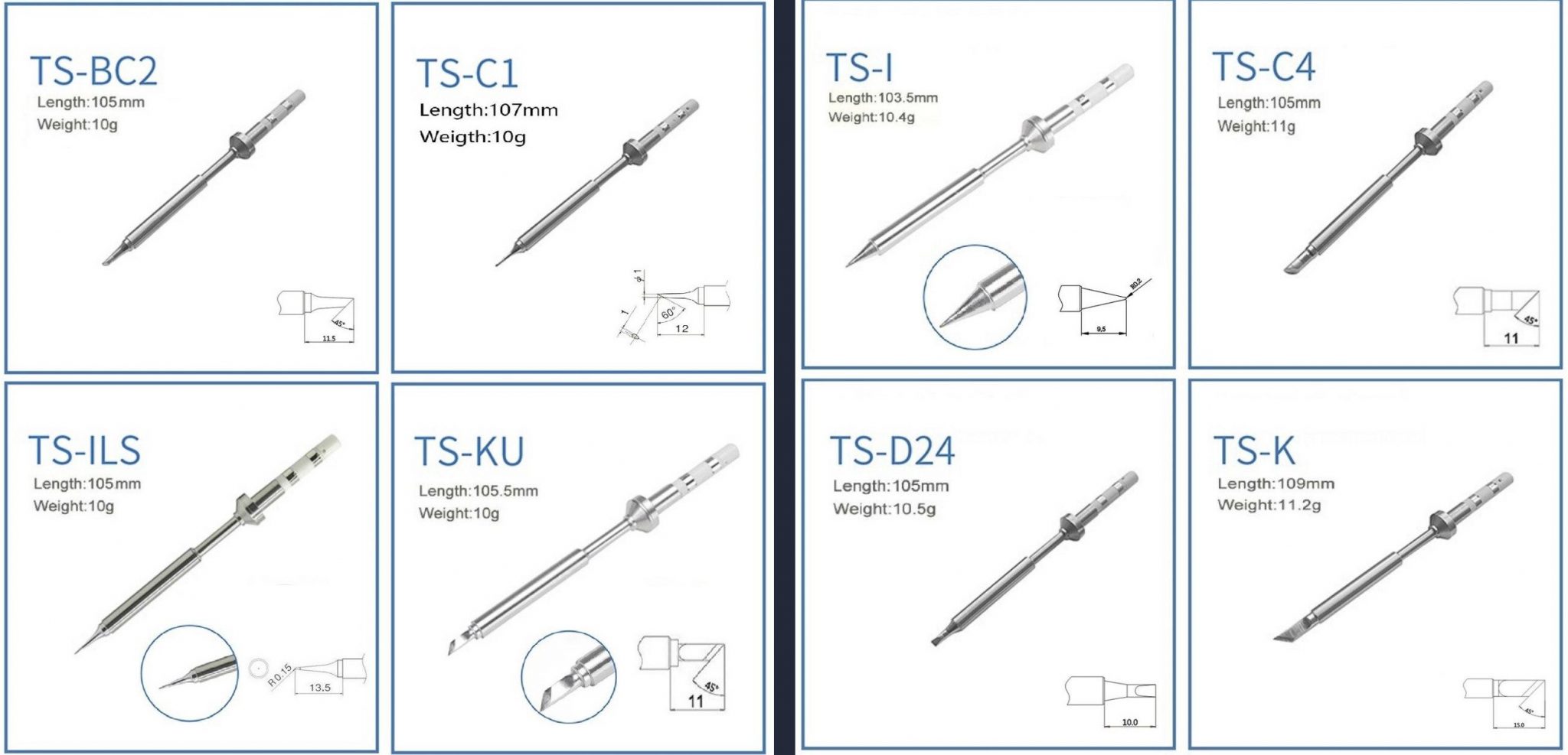
- Soldering tips:
- Replaceable
- More than half a dozen available. Currently sold as 2 separate sets of 4, one fine set, the other larger.
- Compatible with TS100
- Flexible power sources:
- Barrel jack
- USB Type C power delivery
There are additional features that include (Useful for devkit use):
- A Programmable Gigadevice Risc-V GD32V embedded processor
- 0.67" Monochrome Display that can render text or graphics
- Support for Idle detection, for automatic power down of tip
Use
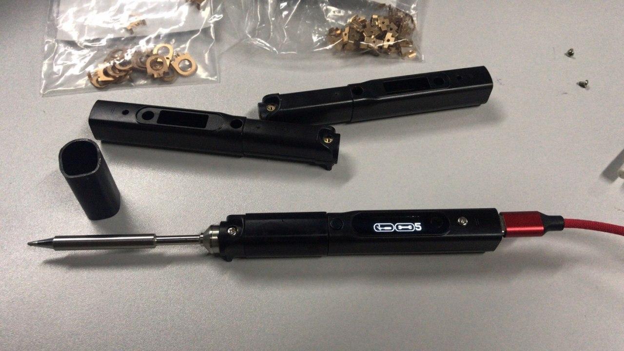
Pinecil comes with a separate heating element / tip. After inserting its barrel into the end of the handle, lightly tighten the screw onto it. Loosen this screw when changing out the tip.
The USB port, connected to any host, provides enough power to drive the user interface, but not necessarily enough to heat the tip. To check the firmware version, hold down the "-" button. It will display something like "v2.14.2425902 17-01-21", suggesting its actual release date, here 2021-01-17. Clicking the "+" button repeatedly reveals various internal settings, such as hardware version, current temperature, time since power-on, and number of motions detected. Clicking "-" returns to the regular display of current temperature, target temperature, and supply voltage. At other times it may show power draw.
To actually heat up the tip, you will need a power supply that can provide 12V or more. This may be a dedicated power supply with a standard barrel connector (+ center, - outside) that supplies anywhere from 12V to 21V, or a USB-C supply that can negotiate up to such a voltage. (You probably have a suitable supply disused in a box somewhere.)
Clicking "+" starts the tip heating. The display then shows power draw, current temperature, supply voltage, and estimated time to reach target temperature. You can adjust the target temperature with further clicks of "+" and "-" buttons. Waiting for the regular display to return, then holding down "-" for a moment turns the heat off. You can watch the temperature measurement go up and down. Certain settings involve holding down both buttons.
The iron will "sleep", switching to a lower temperature, after it has been put down for a short time, and heat up again when it is picked up.
Clicking "-" when heat is off steps through menus to control a variety of settings, such as the sleep temperature, time until sleep, motion sensitivity, temperature units (C or F) etc.
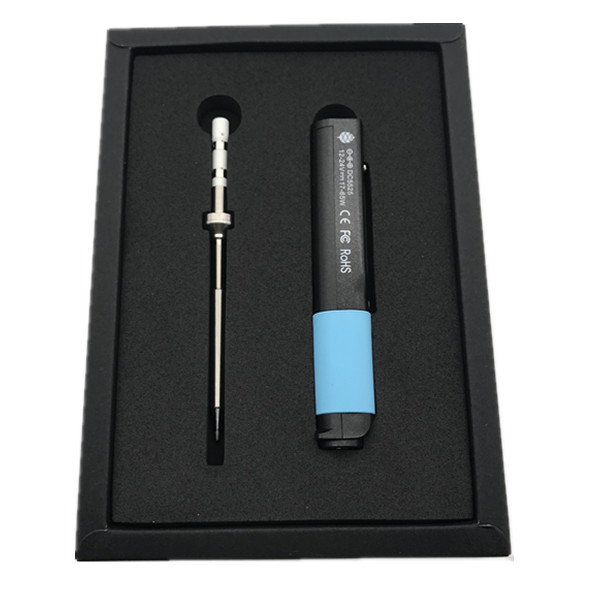
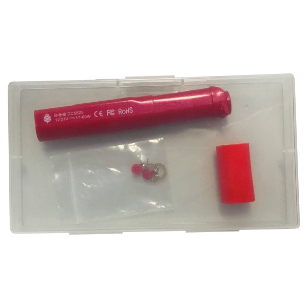
Pictures
Pre-release:
Production:
Pinecil tips
- Uses TS-100 compatible tips
- Tip model TS-B2 is the default tip supplied with the Pinecil
- Tip set 1 (left) & 2 (right):
Specifications
- Dimensions: 170mm with solder tip or 98mm without solder tip x 12.8mm x 16.2mm
- Weight: 30g with solder tip, 20g without solder tip
- CPU: GD32VF103TB 32-bit RV32IMAC RISC-V “Bumblebee Core” @ 108 MHz
- Display: 0.67" QUG 9616TSWCG02 96x16 Monochrome Matrix display
- Memory:
- 128KB Flash
- 32KB SRAM
- DC in (only one of the following at a time):
- 12V- 24V DC5525 Barrel Jack
- USB-C 12-20V PD
- QC3.0
- Recommend operating voltage 12-21V, maximum rating at 24V
Pinecil board information, schematics and certifications
- Pinecil mainboard schematic:
- Pinecil mainboard schematic ver 1.0 20201120, this is production version schematic
- Pinecil mainboard ver 1.0 PCB Component Placement Top PDF file
- Pinecil mainboard ver 1.0 PCB Component Placement Bottom PDF file
- Pinecil mainboard ver 1.0 PCB Component Placement Top Drawing file
- Pinecil mainboard ver 1.0 PCB Component Placement Bottom Drawing file
- Pinecil certifications:
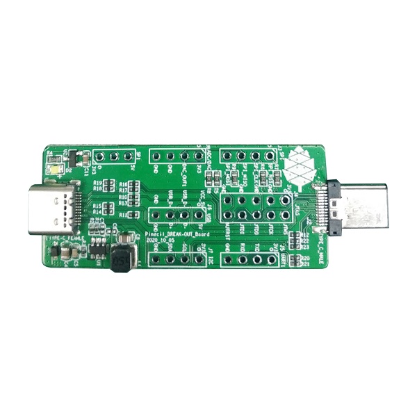
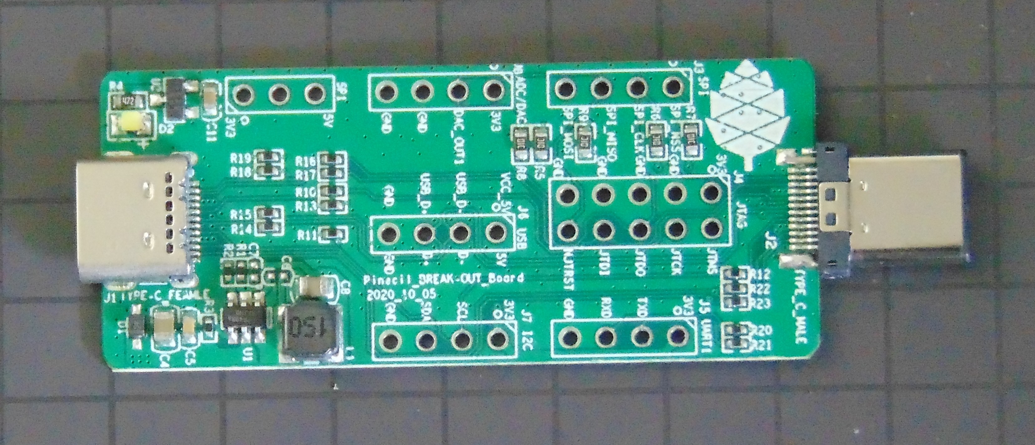
- Pinecil breakout board schematic:
- Photos:
Firmware Image Releases
- Latest Pinecil Firmware Updater for MacOS and Windows
Links to development firmware and documentation:
Datasheets for components and peripherals
- GigaDevice RISC-V SoC information:
- Display Module information:
- USB Type-C PD Controller information:
- Sensor information:
- Power Regulator information:
- Power MOSFET Switch information:
- OP Amp information:
Batch changes
- For the first manufacture batch of the Pinecil, the copper ring connecting the earth screw to the tip was omitted as the engineering team found the TS100 design lacking. For the second round onwards, an improved design copper ring has been included as standard, and is also included with the replacement red and black handles. For normal operation of the iron, omission of the ring does not impact it's operation. If you are working with ESD components, you will however need it in order to ground the iron tip via the earth screw at the back of the iron. If you from the first batch, and need that part, please contact info at pine64 dot org with the subject "Pinecil copper ring", and include your order number and shipment will be arranged.
- The first batch of Pinecil's were rated 12-24v @ 65W. After some heated discussion on the discussion group, it was decided that it would be downgraded to 12-21V @ 60W, due to concern over the connection of the DC jack to the USB-PD chip, which has a recommended maximum of 21v, and absolute maximum of 28v.
Development efforts
| Project Homepage | Project Source | Implementations | |
|---|---|---|---|
| Ralimtek | https://ralimtek.com | https://www.gitmemory.com/Ralim | |
| Alvin Wong | https://github.com/alvinhochun/gd32vf103-pinecil-demo-rs |
How to update a firmware
With application
- Download Pinecil Firmware Updater for Windows, MacOS, or build by yourself from sources.
- Open it, select operating system you want to flash and click *Flash*. (Don't connect Pinecil yet)
- Follow application instructions for correct Pinecil connection to your PC.
Manually
(Method tested on Linux, should work on any OS which supply dfu-util 0.10, if your distro comes with 0.9 you might soft-brick your Pinecil)
dfu-util command cannot find a device with 28e9:0189 ID, try to run it with sudodfu-util -l. If it reports alt=0, name="@Internal Flash /0x08000000/128*001Kg" you are fine, otherwise you need to upgrade to 0.10, important part is 128*001Kg, which is flash amount of blocks and block size, as a chip used in Pinecil have 128 KB of Flash with 1KB page size- Enter an update mode. For that plug USB cable while holding *-* button (button, that's closest to USB-C port)
- Make a firmware backup:
dfu-util -d 28e9:0189 -a 0 -U ~/pinecil/internal.flash.stock -s 0x0800000028e9:0189-- USB Device ID (can be obtained fromlsusbordfu-util -lbut in dfu-util output it might be hard to identify the Pinecil device)-a 0-- selects partition to flash. List of possible options can be obtained viadfu-util -l. Partition 0 - internal SPI flash. Partition 1 - fuses (description of fuses can be found in User Manual for the chip)-U-- specifies a mode. U is upload, which means that firmware will be downloaded and saved to file (yes, that's confusing, but it is what it is, feel free to verify that in a manual of your version of dfu-util). Command must be followed by a path to file where you want to save your firmware. dfu-util will refuse to dump firmware if you already have a file with that name.-s 0x08000000-- specify the address in a flash from which dump will start. This can be obtained fromdfu-util -l.
- Flash a new firmware:
dfu-util -d 28e9:0189 -a 0 -D Pinecil_EN.bin -s 0x08000000:mass-erase:force-D-- is a mode to Download firmware to the device (yes, that's confusing, but you indeed Upload from device and Download to device with dfu-util). That should follow the file with the firmware. Update archive from Ralim usually contains two files:.hexand.bin. One that is required - is.bin._ENis the language code of the firmware, means that_ENwill flash english version of firmware.-s 0x08000000:mass-erase:force-- specified the address where to flash the file.:mass-erase:forceis required to force-erase flash before updating firmware, otherwise you might have unpredictable results.- If it fails with
Error during special command "MASS_ERASE" get_status(as has happened with recent shipments) then use ...-s 0x08000000without attempting "mass-erase".
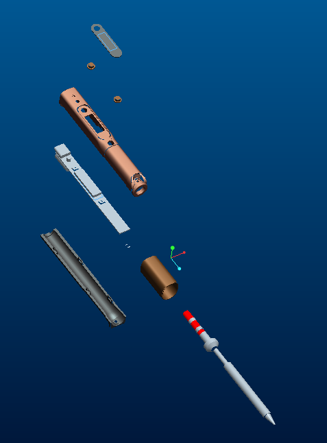
Disassembly steps
- Remove tip if present.
- Let tip cool down.
- Loosen top (display side) screw (PH1) on the tip side of the device.
- Gently pull tip out.
- Slide rubber off towards the tip side.
- Remove the ground screw (longer screw on the top side towards the port side) (PH1).
- Remove the bottom screw (at the tip side, between the legs) (PH1).
- Slightly pull the two halves of the case apart at the tip side, enough to get a fingernail or guitar pick between the halves.
- Move the pick down the length of the split to loosen the bottom half's clips from the top half of the case.
- Once loose, remove the bottom half by moving it forward (it is retained by the top half at the port side).
- Remove the screws retaining the copper tip contacts (PH000).
- Remove the now loose copper tip contacts.
- Gently push the board towards the tip side by pushing on one of the ports (for example, by using a misaligned USB C connector).
- The PCB assembly is now free to be lifted out.
- The key caps are now no longer retained, carefully set aside the top half, or remove the caps and store them separately.
Assembly steps
- Place the key caps into their recesses in the top half of the case.
- Place the PCB assembly into the top half of the case ports first.
- Lower the rest of the board into the case and move the PCB assembly towards the port side of the case (the DC barrel connector may be a firm place to gently push).
- Install the copper tip contacts.
- Orient the contact to align the alignment pin with the alignment hole next to the big hole on one of the big gold pads.
- Install and gently tighten the PH000 screw until the clip is no longer loose.
- Place the bottom half of the case into the top half by sliding the lip on the port side (side without the feet) of the bottom half under the arch of the port side of the top half.
- Gently close the case by bringing the two halves together, paying attention to each clip's alignment and ensuring the case edges align.
- Install the short PH1 screw at the bottom of the tip side of the case.
- Install the longer PH1 screw at the ground connection point at the top side of the case (between the display and the ports).
- Slide the rubber sleeve on (larger ridge first).
- Gently insert tip.
- Gently tighten the top PH1 screw to retain the tip.
Power Supply Compatibility
The Pinecil can either work with a 12-21V battery or power supply via the 5525 (5.5mm outer diameter, 1.5mm post) centre-positive jack, or with any USB power supply that supports the QC2, QC3 or USB-PD (Power Delivery) specification. QC2 and QC3 power supplies will only be able to provide a maximum of 12V, limiting the Pinecil to about 17W of thermal capability. A suitable USB-PD power supply / power bank will be able to provide 20V, allowing the Pinecil to deliver the full 60W of heat to soldering tip.
Known working QC/PD/barrel power adapters / power banks include:
Power adapter:
- PinePower Desktop
- Nekteck 60W with 6ft cable
- Notebook AC Adapter HP L30757-002 (PD@20V)
- Notebook AC Adapter Lenovo ADLX65YLC3D (PD@20V) or LN-A0403A3C (Barrel 20V/2A)
- Notebook AC Adapter Delta Electronics ADP-65JH BB (DC@19V) and ADP-90CD DB
- Notebook AC Adapter LITEON PA-1700-02 (DC@18.5V, 65W)
- Smartphone Charger Samsung EP-TA20EWE (QC2@9V)
- Smartphone Charger Google Pixel G1000-US (PD@9V)
Power bank:
Limited usability:
- Notebook Docking Station HP Thunderbolt Dock 230W G2 (Pinecil Firmware: 2.14.2425902)
- Pinecil switches between PD@20V/unpowered at ~ 0.5 Hz => No settings possible, but halfways works with power on setting or regulary pressing the heat up button
- Works fine when using PDC004-20V or ZY12PDN breakout on dc jack (DC@20V)
- Nillkin 63W USB Car Charger Quick Charge 3.0 PD (Pinecil Firmware: 2.14.2425902)
- QC3@9V/12V and PD@15V work, PD@20V doesn't
- PD@20V works fine when using PDC004-20V or ZY12PDN on dc jack (DC@20V, limit: 45W)
Blacklist / Not compatible:
- Smartphone Charger RAVpower 30W Dual USB Turbo Wall Charger (Should provide QC3@9V/12V, but only provides 5 V on both ports)
Cases and 3D Models
- 3D model of Pinecil by kohkoh
- Pinecil compact case
- Pinecil and tips case
- T12 Tip Adapter
- Thingiverse search for 'Pinecil'
Caring for a soldering iron
https://www.weller-tools.com/how-to-care-for-soldering-iron-tips/
https://www.eevblog.com/forum/beginners/best-way-to-clean-oxidized-soldering-iron-tip/
