PineTime
Specifications
Dimensions: 37.5 x 40 x 11mm
Weight: 38 grams
IP Rating: IP67 (waterproof to 1 meter)
Display:
- Size: 1.3 inches (33mm) diagonal
- Type: IPS capacitive touchscreen, RGB 65K colors
- Display Controller: ST7789
- Resolution: 240x240 pixels
System on Chip: Nordic Semiconductor nRF52832
Flash: 512KB with additional 4MB SPI NOR
RAM: 64KB
Bluetooth: 5.0 (including Bluetooth Low Energy)
Sensors: Accelerometer, Heart rate sensor
Feedback: Vibration motor
Battery: 170-180mAh LiPo
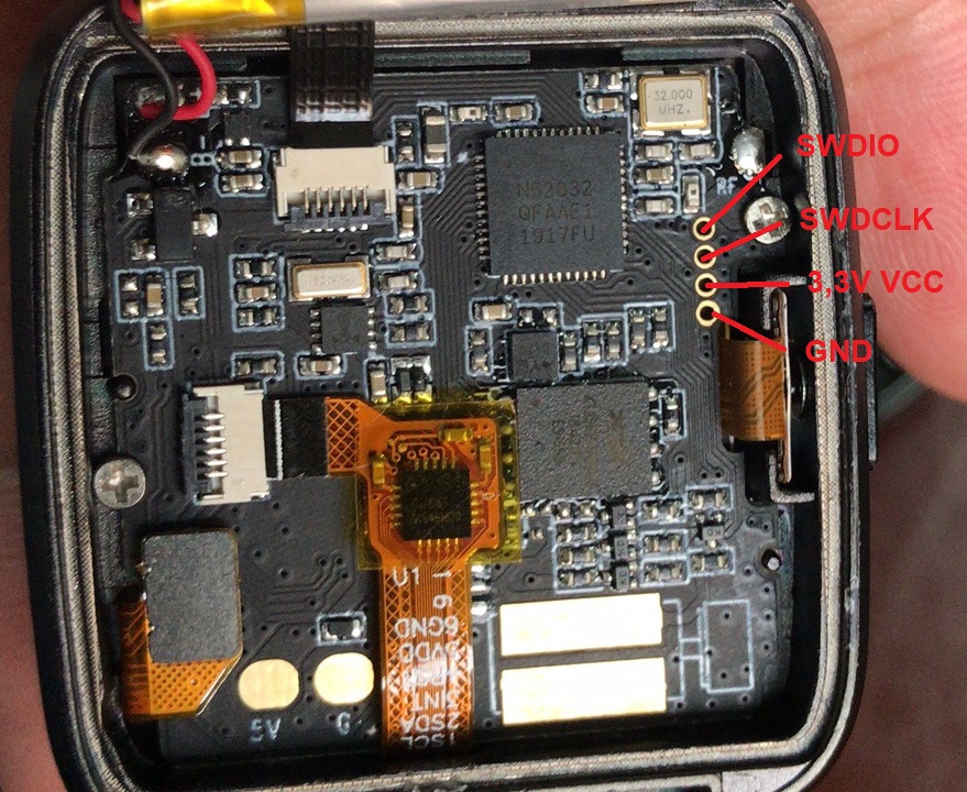
SWD Pinout
The devkits have exposed SWD pins for flashing and debugging. The pinout is:

Driving the peripherals
Display
Note: The factory-default software on the PineTime does not auto-detect the display being disconnected when it has already booted. That can cause garbled output, to fix it just restart the PineTime.
The display is driven using the ST7789 display controller. Use the following pins to drive the screen:
| PineTime pin | ST7789 pin |
|---|---|
| LCD_SCK (P0.02) | SPI clock |
| LCD_SDI (P0.03) | SPI MOSI |
| LCD_RS (P0.18) | Clock/data pin (CD) |
| LCD_CS (P0.25) | Chip select |
| LCD_RESET (P0.26) | Display reset |
| LCD_BACKLIGHT_{LOW,MID,HIGH} | Backlight (active low) |
Notes:
- Chip select must be held low while driving the display. It must be high when using other SPI devices on the same bus (such as external flash storage) so that the display controller won't respond to the wrong commands.
- SPI must be used in mode 3. Mode 0 (the default) won't work.
- LCD_DISPLAY_* is used to enable the backlight. Set at least one to low to see anything on the screen.
- Use SPI at 8MHz (the fastest clock available on the nRF52832) because otherwise refreshing will be super slow.
Battery
Reading whether the PineTime has power attached is easy: simply read the charge indication pin (P0.12). When it is high it is running on battery, when it is low it is charging.
Reading the battery voltage is a bit harder. For that you can use the battery voltage pin on P0.31 (AIN7). The returned value is 12 bits, which means it is 0..4095. You can get the measured voltage with the following formula, assuming a reference voltage of 3.3V (this is configurable in the ADC):
adcVoltage = adcValue / (4095 / 3.3)
The measured voltage is actually half of the actual battery voltage, because the ADC is connected between a voltage divider where both resistors are 1MΩ. This can be corrected by multiplying the value:
batteryVoltage = adcValue * 2 / (4095 / 3.3)
It's often better to avoid floating point values on embedded systems and in this case there is no reason to use float at all, we can just represent the value in millivolts. Therefore the formula can be simplified to:
batteryVoltage = adcValue * 2000 / (4095 / 3.3)
batteryVoltage = adcValue * 2000 / 1241
Converting this voltage to an estimated capacity in percent requires a more complicated algorithm, because Lithium-ion batteries have a non-linear discharge curve.
Github/GitLab
Manual / Articles
Development efforts
| Project Homepage | Project Source | PineTime Implementations | |
|---|---|---|---|
| FreeRTOS | https://www.freertos.org | https://sourceforge.net/projects/freertos/ | JF002/Pinetime |
| Zephyr | https://www.zephyrproject.org | https://github.com/zephyrproject-rtos/zephyr | najnesnaj/pinetime-zephyr |
| mynewt | https://mynewt.apache.org/about/ | https://github.com/apache/mynewt-core | lupyuen/stm32bluepill-mynewt-sensor |
| MbedOS | https://os.mbed.com | https://github.com/ARMmbed/mbed-os | sethitow/mbed-pinetime |
| TinyGo | https://tinygo.org | https://github.com/tinygo-org/tinygo | aykevl/go-smartwatch |
Datasheets and Schematics
Schematics
Component Datasheets
- NORDIC SoC information:
- PMU (Power Management Unit) information:
- SPI Flash information:
- LCD Panel:
- Touchpad information:
- Sensor: