Difference between revisions of "PinePhone 1.2 VCONN Hardware Fix"
m (→Sources and tutorials: fix attribution) |
m (Add to PinePhone category) |
||
| Line 54: | Line 54: | ||
* [https://www.youtube.com/watch?v=ZqOb45N2sMc Vdeo: "The equally stupid way"], workaround video by Dalton, using a soldering iron. Less chances to permanently damage the board than the next if you are handy with a soldering iron, but still high. | * [https://www.youtube.com/watch?v=ZqOb45N2sMc Vdeo: "The equally stupid way"], workaround video by Dalton, using a soldering iron. Less chances to permanently damage the board than the next if you are handy with a soldering iron, but still high. | ||
* [https://www.youtube.com/watch?v=j3jc7Mvn9Eo Video: "The stupid way"] workaround video by Lukasz, with pliers. Slightly damages the circuit board, preventing you from soldering the replacement chips at a later point. You might be fine with this. | * [https://www.youtube.com/watch?v=j3jc7Mvn9Eo Video: "The stupid way"] workaround video by Lukasz, with pliers. Slightly damages the circuit board, preventing you from soldering the replacement chips at a later point. You might be fine with this. | ||
[[Category:PinePhone]] | |||
Revision as of 11:47, 2 September 2020
This page details a hardware fix for an issue that affects some early PinePhone units (fixed since 1.2a included).
The issue was originally reported here by megi.
TODO: Add more pictures and schematics, better reference the fix origin and tradeofs, remove TODOs/FIXMEs.
Affected Units
- (FIXME confirm this) "Project Don't Be Evil" devkit
- (FIXME confirm this)PinePhone v1.0 - Developer batch
- PinePhone v1.1 - Braveheart
- PinePhone v1.2 - Community Edition
Disclaimer
This fix requires desoldering tiny (1 mm per 1 mm, from the datasheet) BGA components, therefore some experience with soldering is highly recommended.
Issue description
The USB standard specifies that both halves (top and bottom) of the USB-C port contains one "CC" pin (CC1 and CC2, respectively). A regular cable will connect a CC pin from one end to the other end. This allows detecting which way the cable is plugged. Some active USB-C cables exist (both "e-marked" and "managed active cables"); they contain a chip, which needs to be powered. This is done by having one of the cable end connect its CC pins to 5V and VCONN, and requires switches to plug the right CC pin to the right voltage.
The issue arises due to the switches that were chosen up to v1.2a (the a revision excluded) of the PCB assembly: the infamous AW3512, labelled U1305 and U1309 on the schematic. Instead of leaving the output pin "dangling" with a high impedance when disabled, the switch pull the output down. This feature is intended for discharging a capacitor, hence its "Quick output discharge" name. This is an excerpt from the datasheet:
The AW3512/AW35122 includes the Quick Output Discharge (QOD) feature, in order to discharge the application capacitor connected on OUT pin.When EN pin is set to low level (disable state), a discharge resistance with a typical value of 276Ω (AW35122: 75Ω)is connected between the output and ground, pull down the output and prevent it from floating when the device is disabled.
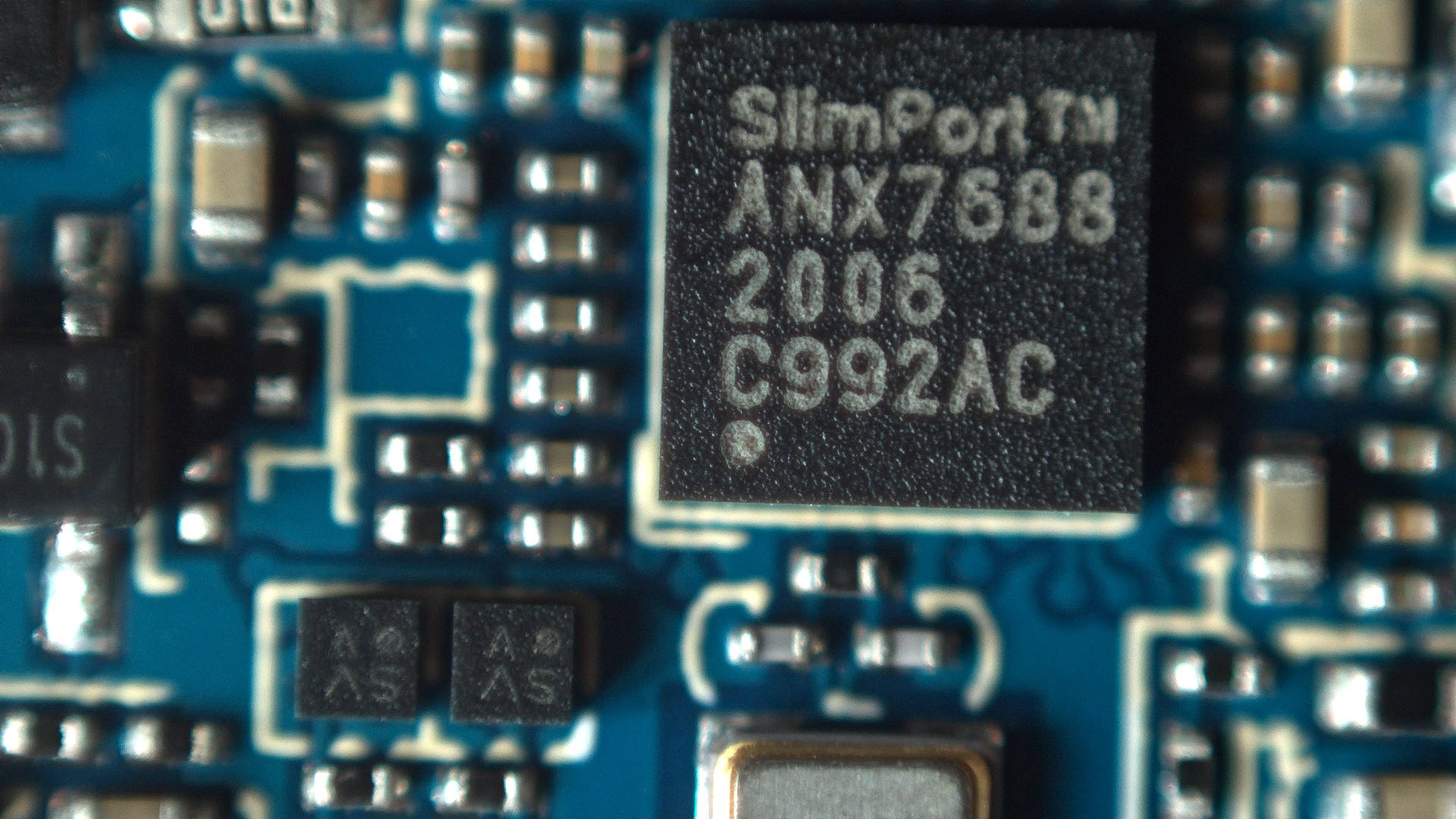
This issue prevents cable plug/orientation detection and USB-PD communication. ANX always sees cable as plugged even if none is plugged. There's no SW workaround for automatic detection of cable plug or power role.
In SW this could theoretically be worked around by manual selection of PinePhone's data and power role by the user, but hasn't been attempted, and might damage hardware if done incorrectly.
Workaround
HW workaround is desoldering U1305 and U1309 switches (BGA like packages). This will void the VCONN control, but it will release the CC pins for their proper connection detection and negotiation roles.
Tradeoffs
Voiding the VCONN control might (TODO: gather more data) prevent some accessories from working, notably those using an active cable.
Proper fix
HW fix is to replace AW3512 with a variant of the chip that preserves the EN signal polarity and that doesn't have the "quick discharge function" that ties the output to the GND via a 75 Ohm resistor when the switch is OFF. mozzwald used NCP334FCT2G as a replacement.
PCBA revision 1.2a onwards should incorporate that fix. (TODO: confirm this).
Sources and tutorials
- megi's writeup
- another writeup from megi with a few words on firmware
- Video: "The right way" with a hot air gun/reflow station, by mozzwald
- Vdeo: "The equally stupid way", workaround video by Dalton, using a soldering iron. Less chances to permanently damage the board than the next if you are handy with a soldering iron, but still high.
- Video: "The stupid way" workaround video by Lukasz, with pliers. Slightly damages the circuit board, preventing you from soldering the replacement chips at a later point. You might be fine with this.

