Difference between revisions of "PineTime"
(→Watch Information: Add PineTime RTOS Comparison link.) |
|||
| Line 42: | Line 42: | ||
* PLATFORM: | * PLATFORM: | ||
** OS: Various open source RTOS such as Zephyr, FreeRTOS, Mbed, Mynewt, or NuttX | ** OS: Various open source RTOS such as Zephyr, FreeRTOS, Mbed, Mynewt, or NuttX. See [[PineTime RTOS Comparison]]. | ||
** SoC: NORDIC Semiconductor nRF52832 (final product may use nRF52840) | ** SoC: NORDIC Semiconductor nRF52832 (final product may use nRF52840) | ||
** CPU: 64MHz ARM Cortex-M4F | ** CPU: 64MHz ARM Cortex-M4F | ||
Revision as of 02:49, 4 November 2019
PINE64 SmartWatch "PineTime"
The PINE64 SmartWatch, dubbed "PineTime", is a product of a community effort for an open source smartwatch in collaboration with wearable RTOS and Linux app developers & communities.
PineTime development has been broken down into two distinct phases:
- Phase One - PineTime Dev Kit Project on October 2019
- Phase Two - Introducing the PineTime smartwatch around Q1 2020, depending on development results in Phase 1.
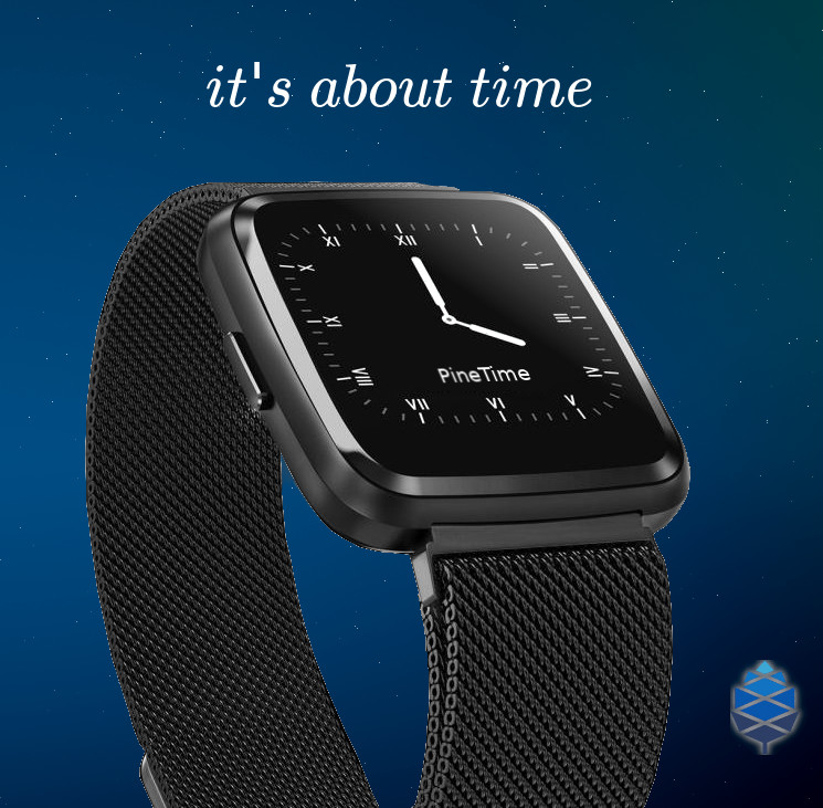
PineTime Concept Photo
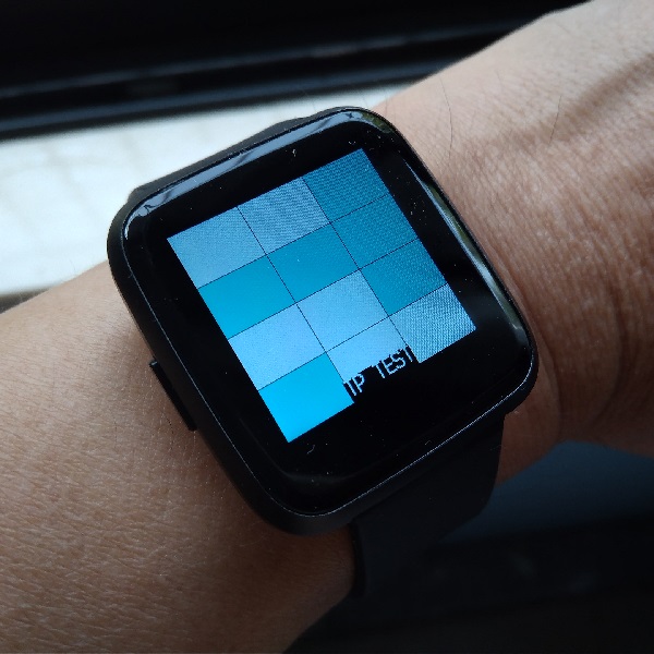
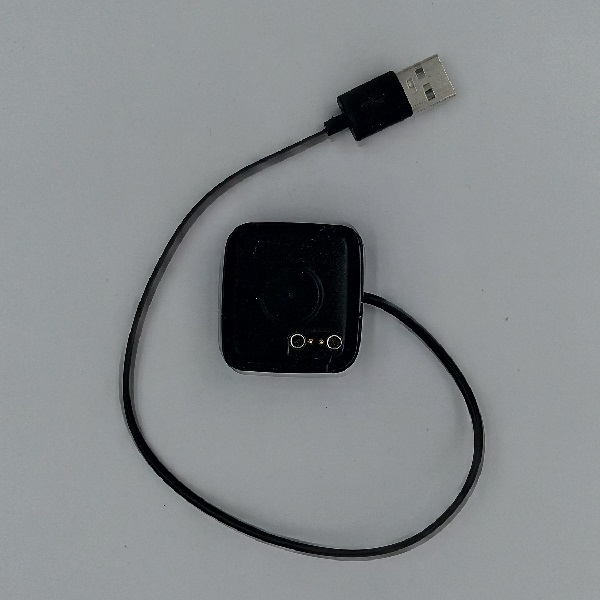
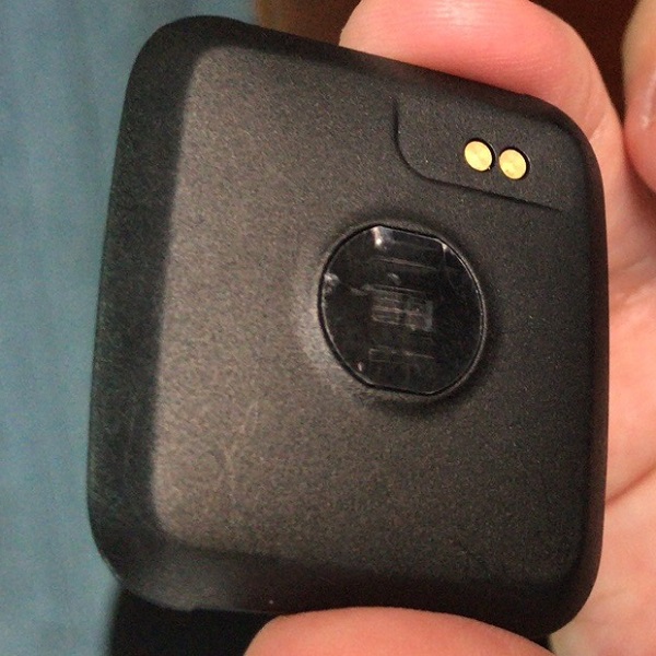
PineTime Case and Charging Cradle Photos
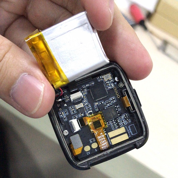
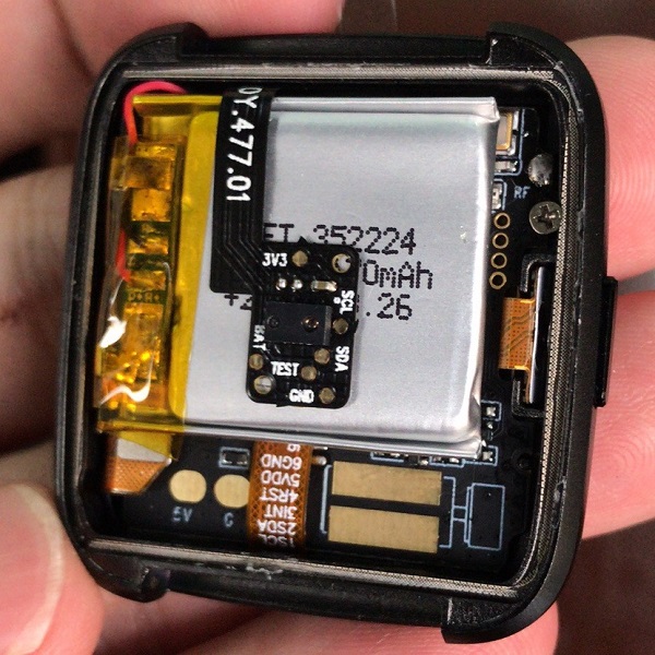
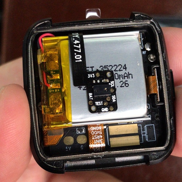
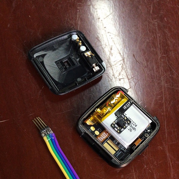
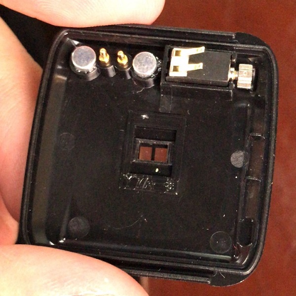
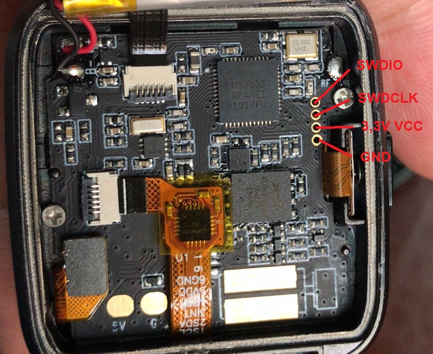
PineTime DevKit internal Photos
Watch Information
- LAUNCH:
- Announced: Tweet on 13 September 2019
- Devkit Release: October, 2019
- Expected Release: Q1/Q2 2020, pending on development result
- Availability: at least 5 years
- BODY:
- Dimensions: 37.5mm x 40mm x 11mm
- Weight: 38 grams
- Build: Zinc Alloy and Plastic
- Environmental Rating: IP67 (waterproof to 1 meter of immersion; not applicable to devkits)
- DISPLAY:
- Type: IPS capacitive touchscreen, RGB 65K colors
- Size: 1.3 inches
- Resolution: 240x240 pixels, 1:1 ratio
- PLATFORM:
- OS: Various open source RTOS such as Zephyr, FreeRTOS, Mbed, Mynewt, or NuttX. See PineTime RTOS Comparison.
- SoC: NORDIC Semiconductor nRF52832 (final product may use nRF52840)
- CPU: 64MHz ARM Cortex-M4F
- MEMORY:
- Internal: 512KB Flash, 64KB RAM (nRF52840: 1 MB flash, 256KB RAM)
- Additional: SPI NOR 8 MB Flash
- COMMUNICATION:
- Bluetooth 5 (including Low Energy)
- FEATURES:
- Sensors: Accelerometer, PPG Heart Rate Sensor
- Actuator: Vibrator
- BATTERY:
- Built-in LiPo 170-180mAh battery
- Charging: Proprietary 2pin 5V 500mA, USB type A plug
- PRICE:
- USD $22.99 (PineTime pebble and charging cradle, based on phone on PineTime devkit hardware configuration)
- USD $2 and up (20mm straight generic wrist band: silicone, NATO, Milanese steel, leather, and etc)
PineTime Schematic and Certifications
- PineTime Main Board Schematic:
- PineTime Certifications:
- not yet available
PineTime DevKit SWD Probe
- PineTime SWD probe pinout definition:
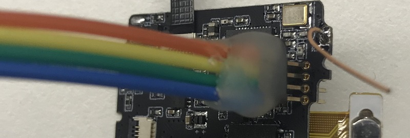
PineTime SWD Probe Usage Method
Slightly bend or zig-zag the probe pins to the left and right to strengthen contact to the SWD pins on the dev kit.
Note: The color coding on the SWD probe wires is random and meaningless.
Driving the peripherals
Display
The display is driven using the ST7789 display controller. Use the following pins to drive the screen:
| PineTime pin | ST7789 pin |
|---|---|
| LCD_SCK (P0.02) | SPI clock |
| LCD_SDI (P0.03) | SPI MOSI |
| LCD_RS (P0.18) | Clock/data pin (CD) |
| LCD_CS (P0.25) | Chip select |
| LCD_RESET (P0.26) | Display reset |
| LCD_BACKLIGHT_{LOW,MID,HIGH} | Backlight (active low) |
Notes:
- Chip select must be held low while driving the display. It must be high when using other SPI devices on the same bus (such as external flash storage) so that the display controller won't respond to the wrong commands.
- SPI must be used in mode 3. Mode 0 (the default) won't work.
- LCD_DISPLAY_* is used to enable the backlight. Set at least one to low to see anything on the screen.
- Use SPI at 8MHz (the fastest clock available on the nRF52832) because otherwise refreshing will be super slow.
Battery
Reading whether the PineTime has power attached is easy: simply read the charge indication pin (P0.12). When it is high it is running on battery, when it is low it is charging.
Reading the battery voltage is a bit harder. For that you can use the battery voltage pin on P0.31 (AIN7). The returned value is 12 bits, which means it is 0..4095. You can get the measured voltage with the following formula, assuming a reference voltage of 3.3V (this is configurable in the ADC):
adcVoltage = adcValue / (4095 / 3.3)
The measured voltage is actually half of the actual battery voltage, because the ADC is connected between a voltage divider where both resistors are 1MΩ. This can be corrected by multiplying the value:
batteryVoltage = adcValue * 2 / (4095 / 3.3)
It's often better to avoid floating point values on embedded systems and in this case there is no reason to use float at all, we can just represent the value in millivolts. Therefore the formula can be simplified to:
batteryVoltage = adcValue * 2000 / (4095 / 3.3)
batteryVoltage = adcValue * 2000 / 1241
Converting this voltage to an estimated capacity in percent requires a more complicated algorithm, because Lithium-ion batteries have a non-linear discharge curve.
Datasheets for Components
- NORDIC SoC information:
- PMU (Power Management Unit) information:
- SPI Flash information:
- LCD Panel:
- Touchpad information:
- Sensor:
