Difference between revisions of "SOEDGE"
Jump to navigation
Jump to search
(Fixes) |
(→SOEDGE Clusterboard resource: Has its own article) |
||
| Line 124: | Line 124: | ||
** [https://files.pine64.org/doc/datasheet/pine64/ePH.pdf 2.0mm PH Type connector specification use in Lithium Battery (VBAT) port and RTC Battery port] | ** [https://files.pine64.org/doc/datasheet/pine64/ePH.pdf 2.0mm PH Type connector specification use in Lithium Battery (VBAT) port and RTC Battery port] | ||
** [https://files.pine64.org/doc/datasheet/pine64/0.5FPC%20Front%20Open%20Connector%20H=1.5.pdf 0.5mm Pitch cover type FPC connector specification use in DSI port, TP port and CSI port] | ** [https://files.pine64.org/doc/datasheet/pine64/0.5FPC%20Front%20Open%20Connector%20H=1.5.pdf 0.5mm Pitch cover type FPC connector specification use in DSI port, TP port and CSI port] | ||
= Debugging = | = Debugging = | ||
Revision as of 11:47, 1 February 2023
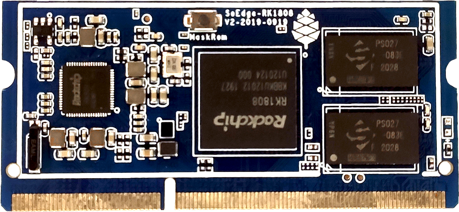
The SOEDGE is a 3TOPS compute module that can be paired with the SOPINE Baseboard or USB 3.0 and PCIe adapters for development. It can connect to a SBC, such as the ROCKPro64 or a regular PC.
Software releases
The SOEDGE software releases can be found in the article SOEDGE Software Releases.
SoC and Memory Specification
- Based on Rockchip RK1808
CPU Architecture
- Dual-core ARM Cortex-A35 Processor@1600-2000Mhz
- A power-efficient ARM 64-Bit Armv8-A architecture
- AArch32 for full backward compatibility with Armv7
- Support NEON Advanced SIMD (Single Instruction Multiple Data) instruction for acceleration of media and signal processing function
- Support Large Physical Address Extensions(LPAE)
- VFPv4 Floating Point Unit
- 32KB L1 Instruction cache and 32KB L1 Data cache
- AArch64 for 64-bit support and new architectural features
- TrustZone security technology
- Neon Advanced SIMD
- DSP and SIMD extensions
- VFPv4 Floating point
- Hardware virtualization support
- 128KB L2 cache
Neural Process Unit NPU Capability
- NPU IP from Verisilicon Vivante
- Support max 1920 Int8 MAC operation per cycle
- Support max192 Int16 MAC operation per cycle
- Support max 64 FP16 MAC operation per cycle
- 512KB internal buffer
- One isolated voltage domain to support DVFS
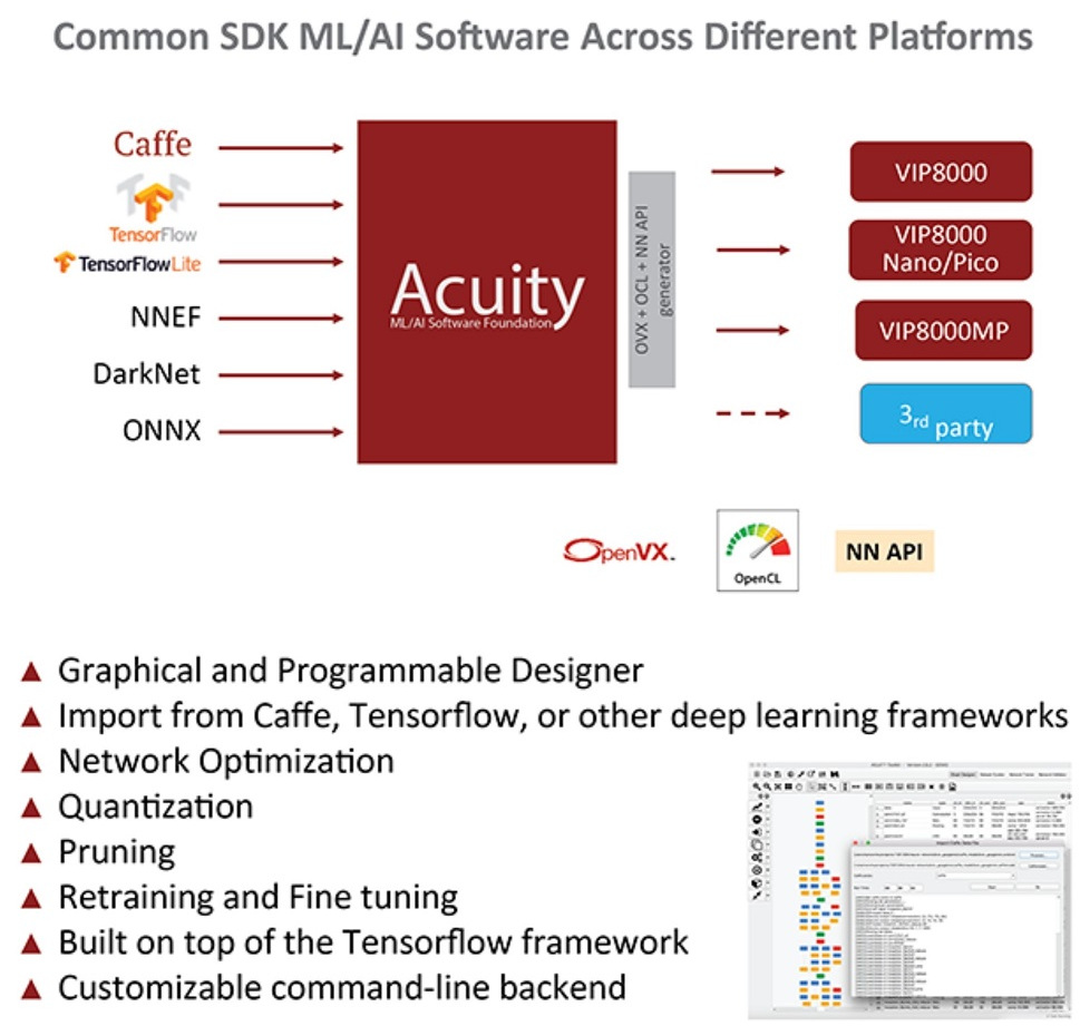
- Acuity models Github
System Memory
- RAM Memory Variants: 2GB DDR4.
- Storage Memory: 128Mb SPI Flash and optional eMMC module from 16GB up to 128GB
SOEDGE Baseboard Features
Network
- 10/100/1000Mbps Ethernet
- WiFi 802.11 b/g/n with Bluetooth 4.0 (optional)
Storage
- microSD - bootable, support SDHC and SDXC, storage up to 256GB
- USB - 2 USB2.0 Host port
Expansion Ports
- DSI - Display Serial Interface, 4 lanes MiPi, up to 1080P
- TP - Touch Panel Port, SPI with interrupt
- RTC - Real Time Clock Battery Connector
- VBAT - Lithium Battery Connector with temperature sensor input
- Wifi/BT Module Header - SDIO 3.0 and UART
- 2x20 pins "Pi2" GPIO Header
- PCIe 2x open ended slot
Schematics and certifications
- Model "A" Baseboard Dimensions: 133mm x 80mm x 19mm
- Input Power: DC 12V @ 3A 5.5OD/2.1ID Barrel DC Jack connector
SOEDGE module schematics:
- SOEDGE Module ver 2.0 20190919 Schematic
- SOEDGE Module ver 2.0 20190919 PCB Component Placement Top PDF file
- SOEDGE Module ver 2.0 20190919 PCB Component Placement Bottom PDF file
- SOEDGE Module ver 2.0 20190919 PCB Component Placement Top Drawing file
- SOEDGE Module ver 2.0 20190919 PCB Component Placement Bottom Drawing file
- SOEDGE Module Pin Assignment ver 1.0 in Excel format(includes comparison chart to SOPine)
- SOEDGE Module Pin Assignment ver 1.0 in Open Document format(includes comparison chart to SOPine)
SOEDGE Model "A" Baseboard schematics and PCB board resources:
- SOEDGE Model "A" Baseboard Schematic 20210223 PDF file
- SOEDGE Model "A" Baseboard 20210223 PCB Component Placement Top PDF file
- SOEDGE Model "A" Baseboard 20210223 PCB Component Placement Bottom PDF file
SOEDGE Neural AI Stick schematic:
SOEDGE/SOPINE/PINE A64 WiFi/BT module schematics:
SOEDGE module together with the baseboard certification:
- Disclaimer: Please note that SOEDGE module is not a "final" product and in general certification is not necessary. However, SOEDGE module still submits the mpdel A baseboard for FCC, CE, and ROHS certifications and obtain the certificates to prove that can pass the testing. Please note, a final commercial product needs to perform its own testing and obtain its own certificate.
- Not yet available
Datasheets for Components and Peripherals
- Rockchip RK1808 SoC information:
- Rockchip RK809 PMU (Power Management Unit) information:
- DDR4 information:
- eMMC information:
- SPI NOR Flash information:
SOEDGE Related:
- LCD Touch Screen Panel information:
- Ethernet PHY information:
- Wifi/BT module information:
- Enclosure information:
- Connector information:
Debugging
Serial Console
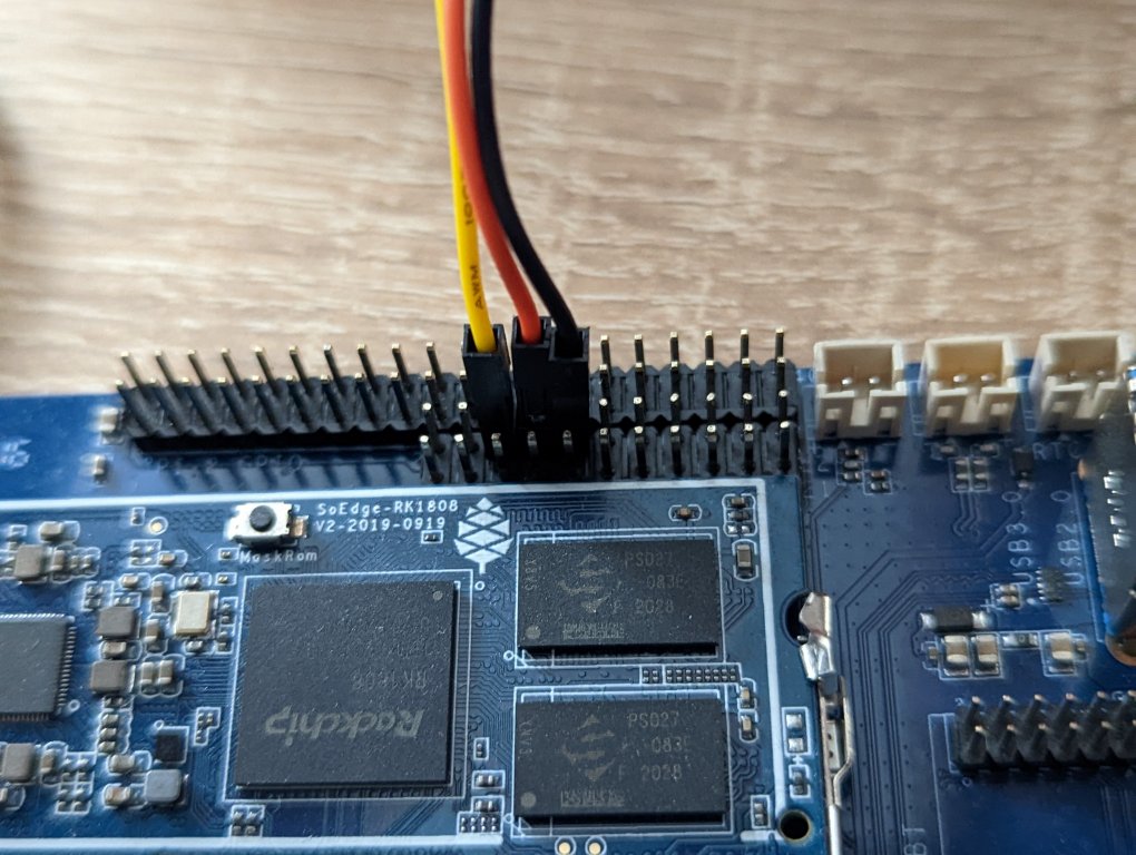
System Serial is located on PI-5 bus (11x2 GPIO header).
- TXD: Pin 6 (Yellow cable) (Connect to RXD on Serial adapter)
- RXD: Pin 8 (Orange cable) (Connect to TXD on Serial adapter)
- GND: Pin 10 (Black cable) (Connect to GND on Serial adapter)
The default baudrate is 1500000, note that not all serial adapters support this high baudrate.
Linux Image Releases
Stock BSP
BSP Linux ver 1.1 Build from SDK
- Please unzip first and then using Rockchip tool to flash in
- Guide to flashing eMMC using Rockchip Tools
- download from pine64.org
- MD5 (TAR-GZip file): a6629f997ae2cae7d9d5324c4e942deda9
- File Size: 119MB
BSP Linux ver 1.1 Build as USB Stick application from SDK
- Please unzip first and then using Rockchip tool to flash in
- Guide to flashing eMMC using Rockchip Tools
- download from pine64.org
- MD5 (GZip file): af6ac45995f7ddd9343a7052efffaf30
- File Size: 47MB
Factory Test Build
- Factory Test Build by Gamiee
- DD image (for 8GB microSD card or eMMC Module and above)
- download from pine64.org
- MD5 (GZip file): b3d09933734eaaebb34c357b73f5c69e
- File Size: 119MB
Linux BSP SDK
Linux BSP Kernel ver 1.1.7
- Direct Download from pine64.org
- MD5 (TAR-GZip file): 47a81a990a644539f3a0e84034654f78
- File Size: 17.42GB
Linux BSP Kernel ver 1.1
- Direct Download from pine64.org
- MD5 (TAR-GZip file): a66c92e52824762d7c0a63400d6342ea
- File Size: 13.55GB
Linux BSP Kernel ver 1.1 as USB Stick application
- Direct Download from pine64.org
- MD5 (TAR-GZip file): 46f12441e8c35c06184681f355c89651
- File Size: 9.65GB


