Difference between revisions of "SOQuartz"
Jump to navigation
Jump to search
(→Datasheets for Components and Peripherals: specify the i2c address of the gp7101 chip, which weirdly enough is half of what the datasheet says) |
Microboars (talk | contribs) |
||
| Line 81: | Line 81: | ||
* 2x20 pins "Pi2" GPIO Header | * 2x20 pins "Pi2" GPIO Header | ||
* PCIe 1x open ended slot | * PCIe 1x open ended slot | ||
=== GPIO Pins === | |||
Attention! GPIOs are 3.3V! | |||
Interesting alternate pin configurations are listed in [brackets]. | |||
{| class="wikitable plainrowheaders" border="1" | |||
! scope="col" style="width:20em;" | Assigned To | |||
! scope="col" | Pin no. | |||
! scope="col" | Pin no. | |||
! scope="col" style="width:20em;" | Assigned To | |||
|- | |||
| style="text-align:right;"| 3.3 V | |||
| style="text-align:center; background-color:yellow; color:black; font-weight:bold;"| 1 | |||
| style="text-align:center; background-color:red; color:gold; font-weight:bold;"| 2 | |||
| style="text-align:left;"| 5 V | |||
|- | |||
| style="text-align:right;"| ''[I2C2_SDA_M1]'' GPIO4_B4_3V3 | |||
| style="text-align:center; background-color:green; color:gold; font-weight:bold;"| 3 | |||
| style="text-align:center; background-color:red; color:gold; font-weight:bold;"| 4 | |||
| style="text-align:left;"| 5 V | |||
|- | |||
| style="text-align:right;"| ''[I2C2_SCL_M1]'' GPIO4_B5_3V3 | |||
| style="text-align:center; background-color:green; color:gold; font-weight:bold;"| 5 | |||
| style="text-align:center; background-color:black; color:gold; font-weight:bold;"| 6 | |||
| style="text-align:left;"| GND | |||
|- | |||
| style="text-align:right;"| ''[GPCLK0]'' GPIO4_A4_3V3 | |||
| style="text-align:center; background-color:green; color:gold; font-weight:bold;"| 7 | |||
| style="text-align:center; background-color:green; color:gold; font-weight:bold;"| 8 | |||
| style="text-align:left;"| UART2_TX GPIO0_D1_3V3 ''[UART2_TX_M0]'' | |||
|- | |||
| style="text-align:right;"| GND | |||
| style="text-align:center; background-color:black; color:gold; font-weight:bold;"| 9 | |||
| style="text-align:center; background-color:green; color:gold; font-weight:bold;"| 10 | |||
| style="text-align:left;"| UART2_RX GPIO0_D0_3V3 ''[UART2_RX_M0]'' | |||
|- | |||
| style="text-align:right;"| ''[I2S1_MCLK_M1]'' GPIO3_C6_3V3 | |||
| style="text-align:center; background-color:green; color:gold; font-weight:bold;"| 11 | |||
| style="text-align:center; background-color:green; color:gold; font-weight:bold;"| 12 | |||
| style="text-align:left;"| GPIO3_C7_3V3 ''[I2S1_SCLK_M1]'' | |||
|- | |||
| style="text-align:right;"| GPIO4_A0_3V3 | |||
| style="text-align:center; background-color:green; color:gold; font-weight:bold;"| 13 | |||
| style="text-align:center; background-color:black; color:gold; font-weight:bold;"| 14 | |||
| style="text-align:left;"| GND | |||
|- | |||
| style="text-align:right;"| GPIO4_A2_3V3 | |||
| style="text-align:center; background-color:green; color:gold; font-weight:bold;"| 15 | |||
| style="text-align:center; background-color:green; color:gold; font-weight:bold;"| 16 | |||
| style="text-align:left;"| GPIO4_A3_3V3 | |||
|- | |||
| style="text-align:right;"| 3.3V | |||
| style="text-align:center; background-color:yellow; color:black; font-weight:bold;"| 17 | |||
| style="text-align:center; background-color:green; color:gold; font-weight:bold;"| 18 | |||
| style="text-align:left;"| GPIO4_A1_3V3 | |||
|- | |||
| style="text-align:right;"| ''[SPI3_MOSI_M0]'' GPIO4_B2_3V3 | |||
| style="text-align:center; background-color:green; color:gold; font-weight:bold;"| 19 | |||
| style="text-align:center; background-color:black; color:gold; font-weight:bold;"| 20 | |||
| style="text-align:left;"| GND | |||
|- | |||
| style="text-align:right;"| ''[SPI3_MISO_M0]'' GPIO4_B0_3V3 | |||
| style="text-align:center; background-color:green; color:gold; font-weight:bold;"| 21 | |||
| style="text-align:center; background-color:green; color:gold; font-weight:bold;"| 22 | |||
| style="text-align:left;"| GPIO4_B1_3V3 | |||
|- | |||
| style="text-align:right;"| ''[SPI3_CLK_M0]'' GPIO4_B3_3V3 | |||
| style="text-align:center; background-color:green; color:gold; font-weight:bold;"| 23 | |||
| style="text-align:center; background-color:green; color:gold; font-weight:bold;"| 24 | |||
| style="text-align:left;"| GPIO4_A6_3V3 ''[SPI3_CS0_M0]'' | |||
|- | |||
| style="text-align:right;"| GND | |||
| style="text-align:center; background-color:black; color:gold; font-weight:bold;"| 25 | |||
| style="text-align:center; background-color:green; color:gold; font-weight:bold;"| 26 | |||
| style="text-align:left;"| GPIO4_A7_3V3 ''[SPI3_CS1_M0]'' | |||
|- | |||
| style="text-align:right;"| ''[I2C3_SDA_M0]'' GPIO1_A0_3V3 | |||
| style="text-align:center; background-color:blue; color:gold; font-weight:bold;"| 27 | |||
| style="text-align:center; background-color:blue; color:gold; font-weight:bold;"| 28 | |||
| style="text-align:left;"| GPIO1_A1_3V3 ''[I2C3_SCL_M0]'' | |||
|- | |||
| style="text-align:right;"| GPIO3_A5_3V3 | |||
| style="text-align:center; background-color:green; color:gold; font-weight:bold;"| 29 | |||
| style="text-align:center; background-color:black; color:gold; font-weight:bold;"| 30 | |||
| style="text-align:left;"| GND | |||
|- | |||
| style="text-align:right;"| GPIO3_D4_3V3 | |||
| style="text-align:center; background-color:green; color:gold; font-weight:bold;"| 31 | |||
| style="text-align:center; background-color:green; color:gold; font-weight:bold;"| 32 | |||
| style="text-align:left;"| GPIO3_D6_3V3 | |||
|- | |||
| style="text-align:right;"| GPIO3_D7_3V3 | |||
| style="text-align:center; background-color:green; color:gold; font-weight:bold;"| 33 | |||
| style="text-align:center; background-color:black; color:gold; font-weight:bold;"| 34 | |||
| style="text-align:left;"| GND | |||
|- | |||
| style="text-align:right;"| ''[I2S1_LRCK_M1]'' GPIO3_D0_3V3 | |||
| style="text-align:center; background-color:green; color:gold; font-weight:bold;"| 35 | |||
| style="text-align:center; background-color:green; color:gold; font-weight:bold;"| 36 | |||
| style="text-align:left;"| GPIO3_D5_3V3 | |||
|- | |||
| style="text-align:right;"| GPIO3_D3_3V3 | |||
| style="text-align:center; background-color:green; color:gold; font-weight:bold;"| 37 | |||
| style="text-align:center; background-color:green; color:gold; font-weight:bold;"| 38 | |||
| style="text-align:left;"| GPIO3_D2_3V3 ''[I2S1_SDI_M1]'' | |||
|- | |||
| style="text-align:right;"| GND | |||
| style="text-align:center; background-color:black; color:gold; font-weight:bold;"| 39 | |||
| style="text-align:center; background-color:green; color:gold; font-weight:bold;"| 40 | |||
| style="text-align:left;"| GPIO3_D1_3V3 ''[I2S1_SDO_M1]'' | |||
|} | |||
Source: Page 11 of [https://files.pine64.org/doc/quartz64/SOQuartz-Model-A-Baseboard-Schematic-20220522.pdf the board schematics]. | |||
== SOQuartz BLADE Baseboard Features == | == SOQuartz BLADE Baseboard Features == | ||
Revision as of 21:26, 28 December 2022
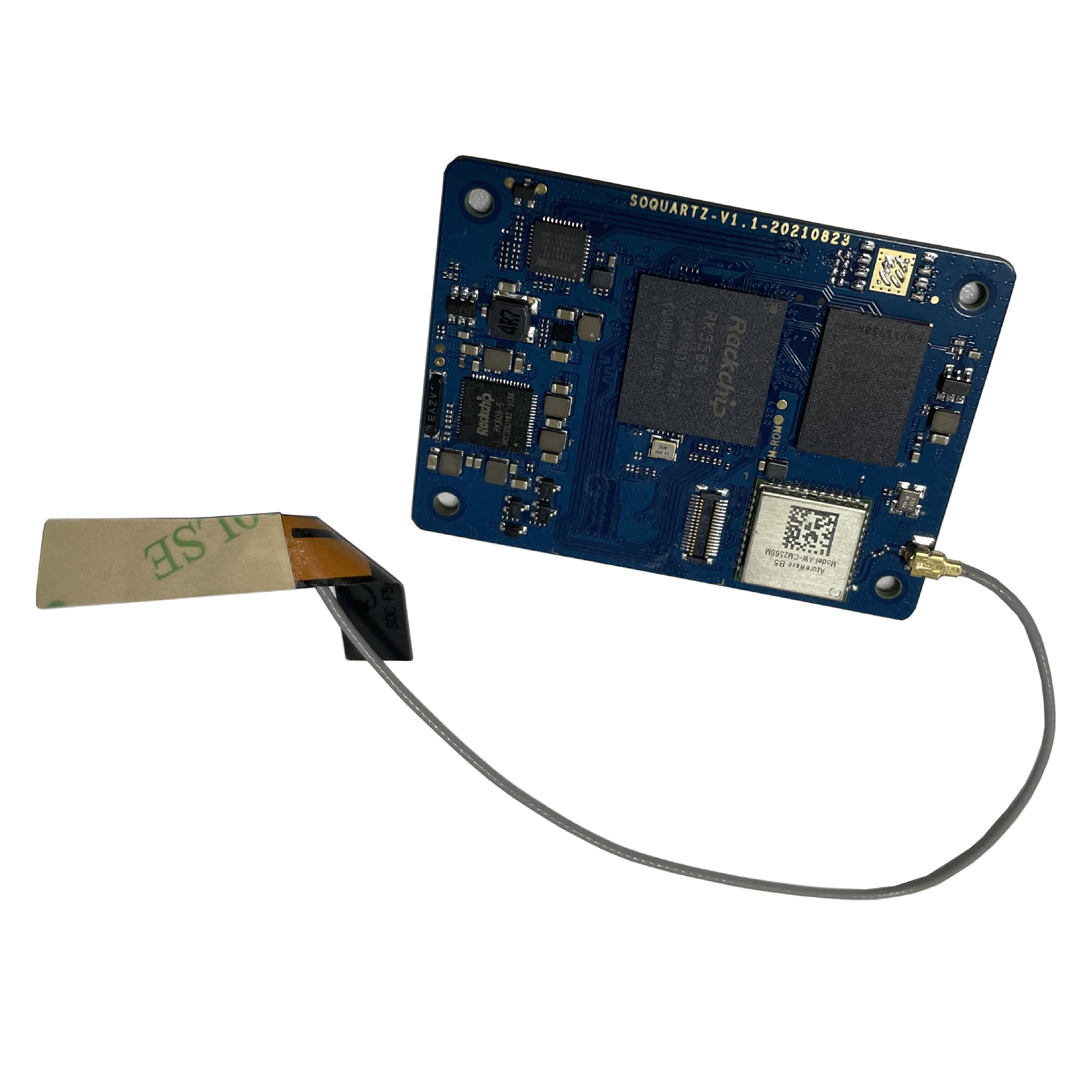
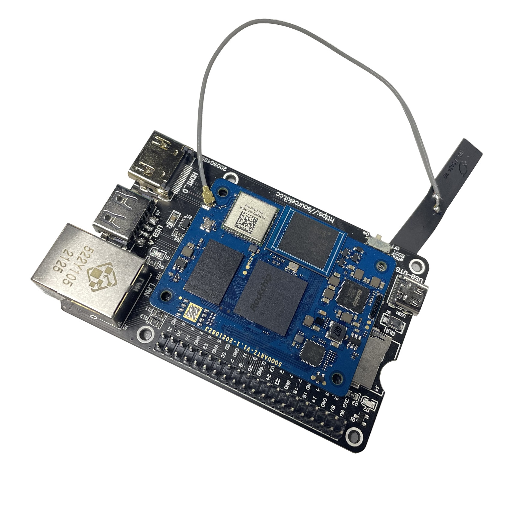
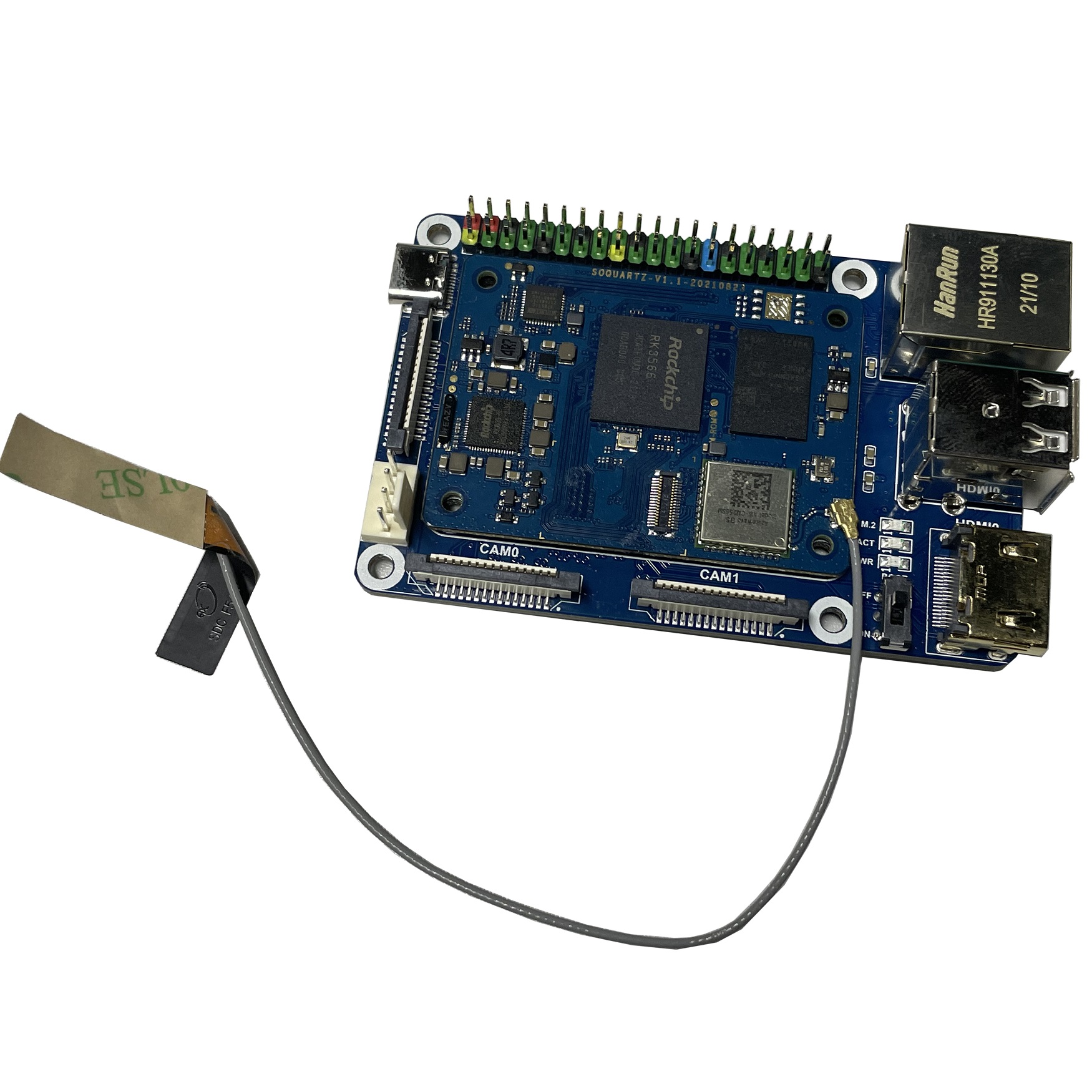
The SOQuartz is a RK3566 based compute module and parts of Quartz64 series.
Software releases
The SOQuartz software releases can be found in the article SOQuartz Software Releases.
SoC and Memory Specification
- Based on Rockchip RK3566
CPU Architecture
- Quad-core ARM Cortex-A55@1.8GHz
- AArch32 for full backwards compatibility with ARMv7
- ARM Neon Advanced SIMD (single instruction, multiple data) support for accelerated media and signal processing computation
- Includes VFP hardware to support single and double-precision operations
- ARMv8 Cryptography Extensions
- Integrated 32KB L1 instruction cache and 32KB L1 data cache per core
- 512KB unified system L3 cache
GPU (Graphics Processing Unit) Capabilities
- Mali-G52 2EE Bifrost GPU@800MHz
- 4x Multi-Sampling Anti-Aliasing (MSAA) with minimal performance drop
- 128KB L2 Cache configurations
- Supports OpenGL ES 1.1, 2.0, and 3.2
- Supports Vulkan 1.0 and 1.1
- Supports OpenCL 2.0 Full Profile
- Supports 1600 Mpix/s fill rate when at 800MHz clock frequency
- Supports 38.4 GLOP/s when at 800MHz clock frequency
Neural Process Unit NPU Capability
- Neural network acceleration engine with processing performance of up to 0.8 TOPS
- Supports integer 8 and integer 16 convolution operations
- Supports the following deep learning frameworks: TensorFlow, TF-lite, Pytorch, Caffe, ONNX, MXNet, Keras, Darknet
System Memory
- RAM Memory Variants: 2GB, 4GB, 8GB LPDDR4.
- Storage Memory: optional 128Mb SPI Flash and optional eMMC module from 16GB up to 128GB
Network
- 10/100/1000Mbps Ethernet
- WiFi 802.11 b/g/n/ac with Bluetooth 5.0
SOQuartz exposed peripherals
Displays / Cameras
- 1x HDMI
- 2x DSI
- 1x eDP (Instead of HDMI1)
- 1x LVDS (not available when dual-mode DSI)
- 1x CSI 4-line
Connectivity
- 1x Ethernet (1Gbit)
- 1x USB 2.0 OTG
- 1x SD Card (SD)
- 1x PCIe 1-Line
- 28x GPIO (TBD)
Connector Pins Definition
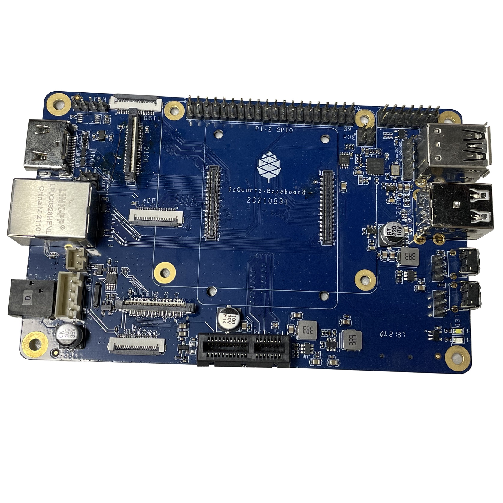
SOQuartz Model-A Baseboard Features
- Model "A" Baseboard Dimensions: 133mm x 80mm x 19mm
- Input Power: DC 12V @ 3A 5.5OD/2.1ID (IEC 60130-10 Type A) Barrel DC Jack connector
Storage
- microSD - bootable, support SDHC and SDXC, storage up to 2TB
- USB - 2 USB2.0 Host port
Expansion Ports
- MiPi-CSI - 1x 2 lanes, 1x 4 lanes
- MiPi-DSI - 1x 2 lanes, 1x 4 lanes
- 2x20 pins "Pi2" GPIO Header
- PCIe 1x open ended slot
GPIO Pins
Attention! GPIOs are 3.3V!
Interesting alternate pin configurations are listed in [brackets].
| Assigned To | Pin no. | Pin no. | Assigned To |
|---|---|---|---|
| 3.3 V | 1 | 2 | 5 V |
| [I2C2_SDA_M1] GPIO4_B4_3V3 | 3 | 4 | 5 V |
| [I2C2_SCL_M1] GPIO4_B5_3V3 | 5 | 6 | GND |
| [GPCLK0] GPIO4_A4_3V3 | 7 | 8 | UART2_TX GPIO0_D1_3V3 [UART2_TX_M0] |
| GND | 9 | 10 | UART2_RX GPIO0_D0_3V3 [UART2_RX_M0] |
| [I2S1_MCLK_M1] GPIO3_C6_3V3 | 11 | 12 | GPIO3_C7_3V3 [I2S1_SCLK_M1] |
| GPIO4_A0_3V3 | 13 | 14 | GND |
| GPIO4_A2_3V3 | 15 | 16 | GPIO4_A3_3V3 |
| 3.3V | 17 | 18 | GPIO4_A1_3V3 |
| [SPI3_MOSI_M0] GPIO4_B2_3V3 | 19 | 20 | GND |
| [SPI3_MISO_M0] GPIO4_B0_3V3 | 21 | 22 | GPIO4_B1_3V3 |
| [SPI3_CLK_M0] GPIO4_B3_3V3 | 23 | 24 | GPIO4_A6_3V3 [SPI3_CS0_M0] |
| GND | 25 | 26 | GPIO4_A7_3V3 [SPI3_CS1_M0] |
| [I2C3_SDA_M0] GPIO1_A0_3V3 | 27 | 28 | GPIO1_A1_3V3 [I2C3_SCL_M0] |
| GPIO3_A5_3V3 | 29 | 30 | GND |
| GPIO3_D4_3V3 | 31 | 32 | GPIO3_D6_3V3 |
| GPIO3_D7_3V3 | 33 | 34 | GND |
| [I2S1_LRCK_M1] GPIO3_D0_3V3 | 35 | 36 | GPIO3_D5_3V3 |
| GPIO3_D3_3V3 | 37 | 38 | GPIO3_D2_3V3 [I2S1_SDI_M1] |
| GND | 39 | 40 | GPIO3_D1_3V3 [I2S1_SDO_M1] |
Source: Page 11 of the board schematics.
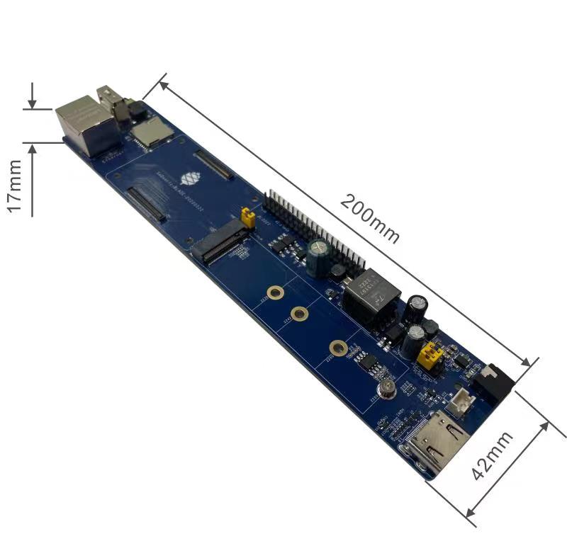
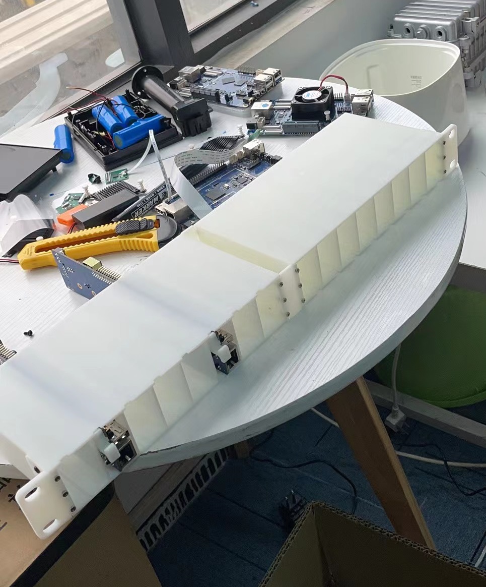
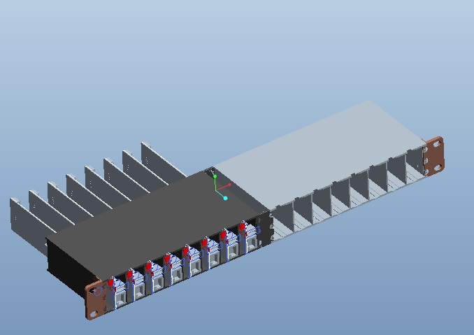
SOQuartz BLADE Baseboard Features
- SOQuartz BLADE Baseboard Dimensions: 200mm x 40mm x 15mm
- Input Power:
- DC 12V @ 3A 3.4OD/1.3ID (IEC 60130-10 Type E) Barrel DC Jack connector
- PoE
Storage
- microSD - bootable, support SDHC and SDXC, storage up to 2TB
- USB - USB2.0 Host port (with header for setting OTG ID pin)
Expansion Ports
- 2x20 pins "Pi2" GPIO Header
- M.2 slot
- PWM fan header
Jumpers
- OTG ID jumper
- GPIO voltage, select 3.3V or 1.8V
- PoE Enable
SOQuartz Module and Baseboard Information, Schematics, and Certifications
- SOQuartz Module Schematic:
- SOQuartz Model "A" Baseboard Schematic and PCB Board Resource:
- SOQuartz Blade Baseboard Schematic and PCB Board Resource:
Datasheets for Components and Peripherals
- Rockchip RK3566 SoC information:
- Rockchip PMU (Power Management Unit) Information:
- DDR4 information:
- eMMC information:
- SPI NOR Flash information:
- Ethernet PHY information:
- WiFi/BT module info:
- i2C to PWM Controller user in BLADE info:
- GP7101 i2c to PWM Controller Datasheet in Chinese
- GP7101 i2c to PWM Controller Datasheet translated to English by neggles File:GP7101 cn V1 qsxn en.pdf
- I2C address is 0x58 despite what datasheet says
- PoE DC/DC Controller user in BLADE info:
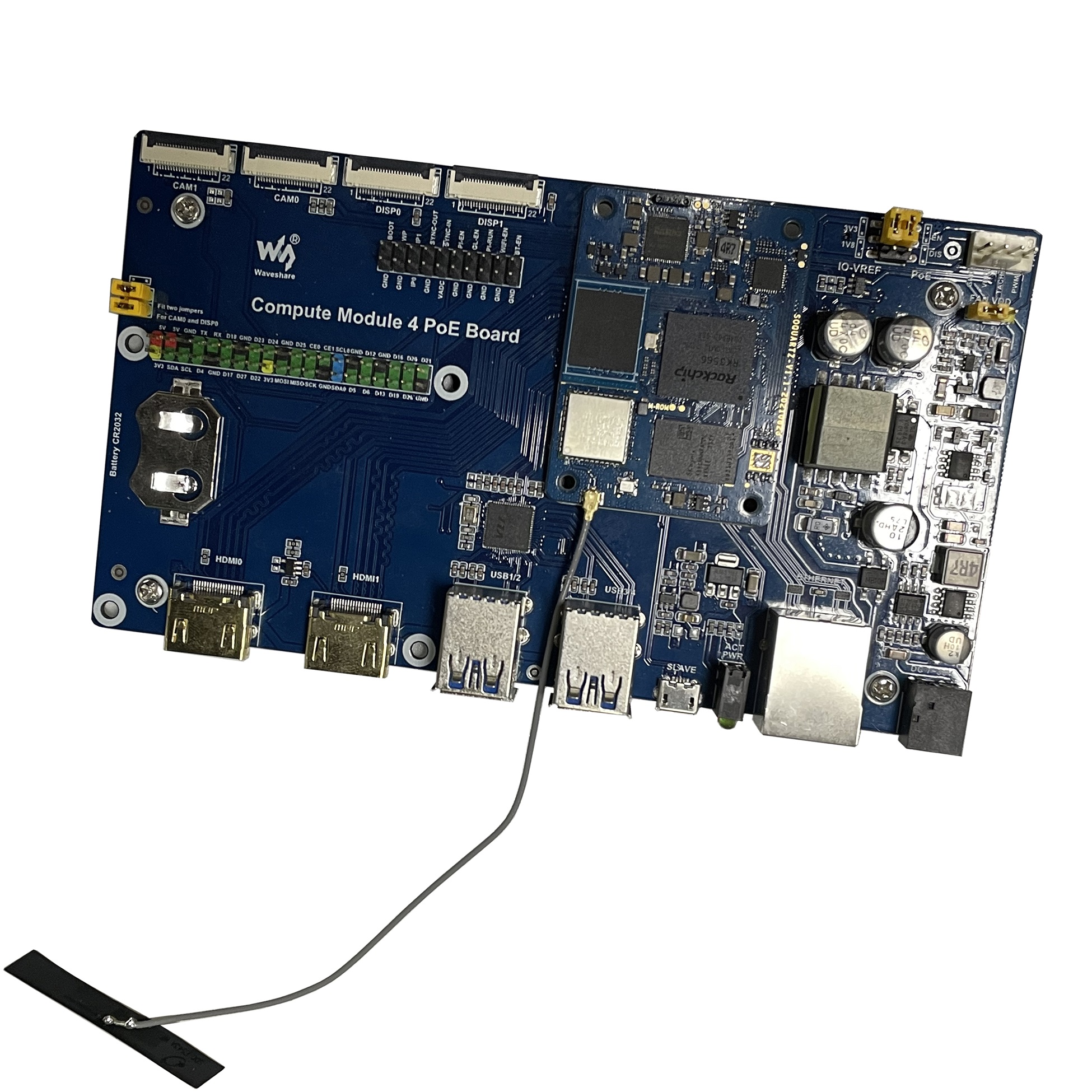
SOQuartz Module with various CM4 carrier boards
- For CM4 carrier board comprehensive list, please visit Jeff Geerling collection
BSP Linux SDK
BSP Linux SDK ver 4.19 for Quartz64 model A SBC
- Direct Download from pine64.org
- MD5 (TAR-GZip file): 24554419aec29700add97167a3a4c9ed
- File Size: 32.67.00GB
Android SDK
Android 11 SDK for Quartz64 model A SBC
- Direct Download from pine64.org
- MD5 (TAR-GZip file): 77c2ff57ea3372fb04da7fb49e17d12b
- File Size: 79.00GB
- Just the boot blobs (<1MB): File:Rk35-blobs.tar.gz
