Difference between revisions of "Oz64"

From PINE64
Jump to navigation Jump to search
(Typo)
 
(22 intermediate revisions by one other user not shown)
Line 1: Line 1:
[[File:Ox64_board.jpg|thumb|right|The Ox64]]
[[File:Oz64_SBC_600x600.jpg|thumb|right|The Oz64 SBC]]
[[File:Ox64 pinout.png|thumb|Pinout of the production version]]
[[File:Oz64_3D_model.png|thumb|right|The Oz64 3D model]]
[[File:RISC-V.png|thumb|right|Powered by RISC-V]]
[[File:RISC-V.png|thumb|right]]


The '''Ox64''' is a RISC-V based single-board computer based on the Bouffalo Lab BL808 RISC-V SoC with C906 64-bit and E907/E902 32-bit CPU cores supported by 64 MB of embedded PSRAM memory, and with built-in WiFi, Bluetooh and Zigbee radio interfaces. The Ox64 comes in a breadboard-friendly form-factor, has a microSD card slot, a USB 2.0 Type-C port, and many other peripheral interfaces for makers to integrate with sensors and other devices.
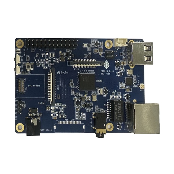
The '''Oz64''' is a low cost single-board computer based on the Sophgo SG2000 SoC with dual T-Head C906 64-bit RISC-V cores, an ARM Cortex A53 64-bit RISC CPU core and an 8051 8-bit core supported by 512 MB of embedded DRAM memory, with WiFi and Bluetooh radio interfaces. The Oz64 SBC comes in a model-B form-factor, has a microSD card slot, an eMMC plugin connector, an USB 2.0 Type-A host port, and many other peripheral interfaces for makers to integrate with sensors and other devices.


== Software Releases ==
Line 9: Line 9:
=== Quick Links to the Source of OS Images Build ===


There is a community effort to bring updated kernels, peripherals and buildroot - Lots of communication happening in the #oz64-nutcracker channel.  
There is a community effort to bring updated kernels, peripherals and buildroot - Lots of communication happening in the #ox64-nutcracker channel.  


* [https://github.com/lupyuen2/wip-nuttx/releases/download/sg2000-1/Image Nuttx Released Image] by Lup Yuen


Toolchain:
Toolchain:
Line 68: Line 69:
[[File:Arm-logo.png|right|200px]]
[[File:Arm-logo.png|right|200px]]


ARM Cortex-A53 1GHzz 64-bit RISC CPU:
ARM Cortex-A53 1GHz 64-bit RISC CPU:


* [https://www.arm.com/products/processors/cortex-a/cortex-a53-processor.php Quad-core Cortex-A53 up to 1.0GHz CPU]
Line 97: Line 98:
=== Storage ===
=== Storage ===
* On-board eMMC module socket
* MicroSD, supports SDHC and SDXC (only on the 128 Mbit version)
* MicroSD, supports SDHC and SDXC


=== Expansion Ports ===
* USB 2.0 Host port
* USB 2.0 Host port
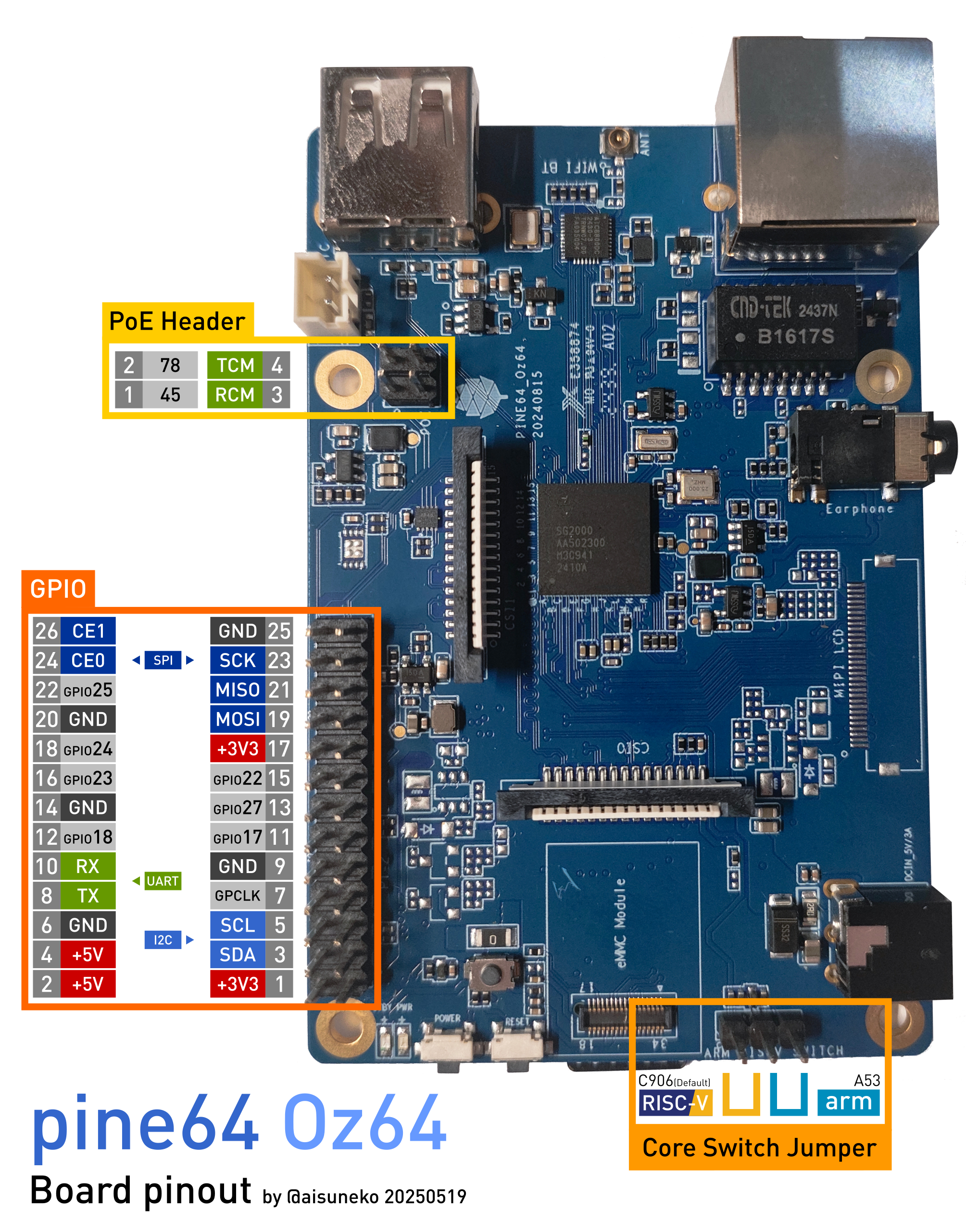
* 26 GPIO pins, including SPI, I<sup>2</sup>C and UART functionality
* Dual-lane MiPi CSI port
* 2x Dual-lane MiPi CSI port
* Dual-lane MiPi DSI port
* Optional dual-lane MiPi DSI port


== Board Information, Schematics and Certifications ==
[[File:Ox64 ethphy.png|thumb|Pinout for wiring ethernet PHY to EMAC]]


* Baseboard dimensions: 51 mm x 21 mm x 19 mm x 3.5 mm (breadboard friendly)
Board Dimensions: 85mm x 56mm x 18.8mm, see the [https://files.pine64.org/doc/rock64/rock64%20board%20dimension.pdf model-B board dimension drawing]
* Input power: 5 V, 0.5 A through the microUSB or USB-C ports


Production version schematic:
Input Power: +5V @2A with 3.5mm/1.35mm Type H Barrel type DC connector (@1.5A will work if there is no heavy load on the USB 2.0 port)


* [https://files.pine64.org/doc/ox64/PINE64_Ox64-Schematic-202221018.pdf Ox64 Schematic 20221018 v1.1]
Pre-Production version schematic:
* [https://files.pine64.org/doc/ox64/PINE64_Ox64_PCB_Placement-Top-20221018.pdf Ox64 PCB Component placement(ToP) 20221018 v1.1]
* [https://files.pine64.org/doc/ox64/PINE64_Ox64_PCB_Placement-Bottom-20221018.pdf Ox64 PCB Component placement(Bottom) 20221018 v1.1]


Prototype (dispatched to developers) schematic:
* [https://files.pine64.org/doc/oz64/PINE64_Oz64_Schematic-20240517.pdf Oz64 Schematic 20240517 v1.0.0]
* [https://files.pine64.org/doc/ox64/PINE64_Ox64-Schematic-202221007.pdf Ox64 Schematic 20221007 v1.0]
* [https://files.pine64.org/doc/oz64/PINE64_Oz64_PCB_Placement-Top-20240517.pdf Oz64 PCB Component placement(ToP) 20240517 v1.0.0]
* [https://files.pine64.org/doc/ox64/PINE64_Ox64_PCB_Placement-Top-20221007.pdf Ox64 PCB Component placement(ToP) 20221007 v1.0]
* [https://files.pine64.org/doc/oz64/PINE64_Oz64_PCB_Placement-Bottom-20240517.pdf Oz64 PCB Component placement(Bottom) 20240517 v1.0.0]
* [https://files.pine64.org/doc/ox64/PINE64_Ox64_PCB_Placement-Bottom-20221007.pdf Ox64 PCB Component placement(Bottom) 20221007 v1.0]


Certifications:
Certifications:
Line 131: Line 127:


Wifi/BT information:
* [https://files.pine64.org/doc/datasheet/ox64/gd25lq16e_rev1.2_20210108.pdf AIC Semi AIC8800DC Datasheet]
* [https://files.pine64.org/doc/datasheet/oz64/AIC8800DC%20Datasheet%20v1.0.pdf AIC Semi AIC8800DC Datasheet]


Power Regulator information:
* [https://files.pine64.org/doc/datasheet/ox64/IA2014-03.pdf Innovation Analog Tech IA2014 Step_down Converter Datasheet]
* [https://files.pine64.org/doc/datasheet/oz64/ETA3414_V1.6.pdf Empower ETA3414 1.5A 3MHz Step_down Converter Datasheet]
* [https://files.pine64.org/doc/datasheet/oz64/ETA3418_V1.4.pdf Empower ETA3418 2.5A 3MHz Step_down Converter Datasheet]
* [https://files.pine64.org/doc/datasheet/oz64/ETA5050_V2.4.pdf Empower ETA5050 500mA Low Noise, High PSRR, Fast Transient Response LDO Datasheet]


MicroSD socket information:
* [https://files.pine64.org/doc/datasheet/ox64/TF%20PUSH%20type%20socket%20specification.pdf Push type microSD socket specification]
== Compatible UARTs when in bootloader mode ==
When the Ox64 is in bootloader mode, some UARTs are unable to communicate with it. When this is the case, utilities such as BLDevCube are unable to actually program the device. If you see "Shake hand fail" and an empty ack, and your device is in bootloader mode, then it is likely an incompatible UART.
The below devices have been tested and verified as working:
* Raspberry Pi Pico - running the following [https://github.com/sanjay900/ox64-uart/releases/tag/v1.1 UART firmware] (GP4 and GP5 are used for port 0, GP12 and GP13 for port 1)
* Compiled binary for Pi Pico and connectivity diagram is [https://github.com/Kris-Sekula/Pine64_Ox64_SBC/tree/main/uart here]
* ESP32 with CP210x - bridge the EN pin to ground to disable the ESP32 itself, and then connect the TX on the esp32 to 14 on the Ox64 and RX to pin 15. Note that only baud rate 115200 works, and this doesn't seem to work for everyone)
* Stand-alone CP2102 dongle works at 115200 baud. Brand used was HiLetgo.
* STM32F401 BlackPill - running the [https://github.com/blackmagic-debug/blackmagic/tree/main/src/platforms/blackpillv2 Black Magic Debug] firmware
* STM32F103C8T6 BluePill - running Black Magic Debug.
* Some UART adapters based on the FT232H (note that the FT232RL does not work, and neither does the Pine 64 JTAG)
* Some CH340G based adapters work and some don't.


== Resources and Articles ==
* [https://youtube.com/watch?v=czRtF-UNiEY A short video] on how to connect to the Ox64, flash and boot
* [https://youtu.be/vPAk5sq_Ilc Another video] that covers soldering pins, connecting via Pi Pico and flashing Linux and U-Boot
* [https://wiki.pine64.org/images/5/59/How_to_Run_Ox64.pdf Step-by-step tutorial] for how to build, flash and run Ox64
* [https://gist.github.com/lupyuen/7a0c697b89abccda8e38b33dfe5ebaff First batch of Ox64 won't appear as USB serial port]
* [https://gist.github.com/lupyuen/2087e9b3fb40aab5e0795bb02a265a3b First batch of Ox64 tested OK with CH340C/G]
* [https://www.robertlipe.com/bl808-not-symmetric/ First thoughts on the (a)symmetry of Bouffalo Labs BL808 as in Pine64 Ox64]
* [https://thelittleengineerthatcould.blogspot.com/2022/12/the-8-linux-computer-part-2.html The $8 linux computer (with picoprobe-rp2040 programming instructions)]
* [https://github.com/p4ddy1/pine_ox64/blob/main/build_toolchain_macos.md Building the Xuantie GNU Toolchain for Ox64 on macOS and Apple Silicon]
Ox64 BL808 RISC-V SBC articles by [https://lupyuen.codeberg.page/ Lup Yuen LEE]:
* [https://lupyuen.codeberg.page/articles/ox64.html Booting Linux and (maybe) Apache NuttX RTOS]
* [https://lupyuen.codeberg.page/articles/ox2.html Starting Apache NuttX real-time operating system]
* [https://lupyuen.codeberg.page/articles/mmu.html Sv39 Memory Management Unit]
* [https://lupyuen.codeberg.page/articles/app.html NuttX Apps and Initial RAM Disk]
* [https://lupyuen.codeberg.page/articles/plic2.html UART Interrupt and Platform-Level Interrupt Controller (PLIC)]
* [https://lupyuen.codeberg.page/articles/plic3.html Fixing the UART Interrupt and Platform-Level Interrupt Controller]
* [https://www.hackster.io/lupyuen/8-risc-v-sbc-on-a-real-time-operating-system-ox64-nuttx-474358 $8 RISC-V SBC on a Real-Time Operating System: Ox64 + NuttX]
* [https://lupyuen.codeberg.page/articles/nim.html Nim on a Real-Time Operating System: Apache NuttX RTOS + Ox64 BL808 SBC]
Git repositories:
* [https://github.com/sfranzyshen/arduino-bl808 Community made Arduino Core specifically for the Bouffalo Labs BL808 RISC-V MCU] (initial development has been postponed until further notice)


== Development Efforts ==
* [https://twitter.com/gamelaster/status/1583916501400068096 Ox64 boots Linux successfully]
* [https://twitter.com/btashton/status/1586381334439923713?t=w5xRRUR74HGK2O1Zg_aFyw&s=19 Brennan Ashton is porting Apache NuttX RTOS and OpenAMP (Asymmetric Multiprocessing) to BL808]
* [https://twitter.com/thanos_engine/status/1585153938092761093 Phone Concept for BL808]


== Build==
== Build==
Open the terminal and create a new directory for the build:
cd ~/Downloads/ox64
mkdir buildroot_bouffalo && cd buildroot_bouffalo
Clone the primary Buildroot repository and the specific Buildroot Bouffalo repository:
git clone https://github.com/buildroot/buildroot
git clone https://github.com/openbouffalo/buildroot_bouffalo
Define an environment variable for the Buildroot Bouffalo overlay path:
export BR_BOUFFALO_OVERLAY_PATH=$(pwd)/buildroot_bouffalo
Change directory into the cloned Buildroot folder:
cd ~/Downloads/ox64/buildroot_bouffalo/buildroot
Apply the default configuration for Pine64 Ox64:
make BR2_EXTERNAL=$BR_BOUFFALO_OVERLAY_PATH pine64_ox64_defconfig
# make clean # deletes all the already compiled object files
Use the <code>menuconfig</code> tool to adjust the build settings:
make menuconfig
[[File:target ABI setting.png|thumb|right|200px|target ABI setting]]
[[File:toolchain setting.png|thumb|right|200px|toolchain setting]]
Within <code>menuconfig</code>, configure the following:
* Navigate to <code>Target Options</code>
* Enable <code>Integer Multiplication and Division (M)</code>
* Enable <code>Atomic Instructions (A)</code>
* Enable <code>Single-precision Floating-point (F)</code>
* Enable <code>Double-precision Floating-point (D)</code>
* Set <code>Target ABI</code> to <code>lp64d</code>
* Under <code>Toolchain</code>, enable <code>Fortran support</code> and <code>OpenMP support</code>
Initiate the build process, but make sure first that your <code>PATH</code> variable contains no spaces:
make
You will get the image files required for flashing in the <code>output/images</code> directory
== Flashing Ox64 SBC and microSD Card ==
This section explains how to flash an Ox64 board and a microSD card to boot the system.
=== Prepare the Environment ===
You need a Linux machine, a Raspberry Pi Pico to act as a UART adapter, the Ox64 board, and a microSD card.
Start a terminal session and set the working directory to download some files.
cd ~/Downloads
mkdir ox64 ox64/pico
cd ~/Downloads/ox64/pico
wget https://github.com/Kris-Sekula/Pine64_Ox64_SBC/blob/main/uart/picoprobe.uf2
cd ~/Downloads/ox64
mkdir ox64/devcube
cd ~/Downloads/ox64/devcube
Get the DevCube 1.8.8 flasher from one of mirror servers listed below.
* https://dev.bouffalolab.com/media/upload/download/BouffaloLabDevCube-v1.8.8.zip
Verify the file hashes listed below.
* SHA1: <code>0f2619e87d946f936f63ae97b0efd674357b1166</code>
* SHA256: <code>e6e6db316359da40d29971a1889d41c9e97d5b1ff1a8636e9e6960b6ff960913</code>
Finally, uncompress the downloaded archive; for example:
wget https://dev.bouffalolab.com/media/upload/download/BouffaloLabDevCube-v1.8.8.zip
sha256sum BouffaloLabDevCube-v1.8.8.zip
unzip BouffaloLabDevCube-v1.8.8.zip
chmod u+x BLDevCube-ubuntu
Download compressed file from https://github.com/openbouffalo/buildroot_bouffalo/releases/ and decompress it.
(You can also get the compressed the file from https://github.com/openbouffalo/buildroot_bouffalo/releases/download/v1.0.1/bl808-linux-pine64_ox64_full_defconfig.tar.gz)
cd ~/Downloads/ox64
mkdir openbouffalo && cd openbouffalo
wget https://github.com/openbouffalo/buildroot_bouffalo/releases/download/v1.0.1/bl808-linux-pine64_ox64_full_defconfig.tar.gz
tar -xvzf bl808-linux-pine64_ox64_full_defconfig.tar.gz
You'll need the following files for the flashing process.
* <code>m0_lowload_bl808_m0.bin</code>
* <code>d0_lowload_bl808_d0.bin</code>
* <code>bl808-firmware.bin</code>
* <code>sdcard.img</code>
=== Establish Serial Communication from PC to Ox64 using Pi Pico ===
Open a terminal and check the connected USB serial devices.
ls /dev/ttyACM*
Set the Raspberry Pi Pico board into programming mode.
* Press the BootSel button
* Apply power by plugging the USB cable to PC
* Release the BootSel button
''Note: you could also ground pin28 to TP6 while powering.''
Copy <code>picoprobe.uf2</code> file into the new device <code>/media/<user>/RPI-RP2</code>.
cp ~/Downloads/ox64/pico/picoprobe.uf2 /media/<user>/RPI-RP2
After flashing, the device will auto-set in serial UART communication mode according to the following wiring diagram.
[[File:Pine Serial v2.png|thumb|right|Wiring Raspberry Pi Pico to Pine64 Ox64 SBC]]
OX64                      PI PICO
uart0_Tx_GPIO14_pin1 <->  uart0_Rx_pin17
uart0_Rx_GPIO15_pin2 <->  uart0_Tx_pin16
Rxd_GPIO17_pin31    <->  uart1_Tx_pin6
Txd_GPIO16_pin32    <->  uart1_Rx_pin7
gnd_pin38            <->  gnd_pin38/3   
vbus5v_pin40        <->  vbus5v_pin40
=== Flash Your Ox64 ===
There are two new ports to choose from, <code>/dev/ttyACM0</code> for serial console and <code>/dev/ttyACM1</code> for DevCube flashing.
minicom -b 2000000 -D /dev/ttyACM0
Set the Ox64 board into programming mode.
* Press the BOOT button
* Apply power or re-plug the USB cable
* Release the BOOT button
Close <code>minicom</code>. Open a new terminal window to run the DevCube flasher.
cd ~/Downloads/ox64/devcube
./BLDevCube-ubuntu
Select chip [BL808], press Finish and switch to [MCU] tab.
M0 Group[group0] Image Addr [0x58000000] [PATH to m0_lowload_bl808_m0.bin]
D0 Group[group0] Image Addr [0x58100000] [PATH to d0_lowload_bl808_d0.bin]
Interface: UART
Port/SN: /dev/ttyACM1 (make sure you don't use /dev/ttyACM0, it's used by the minicom console)
Uart rate 2000000
UART TX is physical pin 1/GPIO 14.
UART RX is physical pin 2/GPIO 15.
Click 'Create & Download' and wait until it's done
Switch to the [IOT] tab.
Enable 'Single Download', set Address with 0x800000, choose [PATH to bl808-firmware.bin]
Port/SN: /dev/ttyACM1 (make sure you don't use ACM0, it's used by minicom console)
Click 'Create & Download' again and wait until it's done
Close DevCube
==== Open-Source Flashing Using CLI ====
For those who do not want to use the DevCube, BouffaloLab provides open-source flashing packages <code>bflb-iot-tool</code> and <code>bflb-mcu-tool</code>.
''Note: While these packages do contain binaries in addition to the Python source code, those binaries do not appear to be used for UART flashing.''
First, install <code>bflb-iot-tool</code> using your preferred method of managing PIP packages. One option is to set up a Python virtual environment as follows.
sudo apt install virtualenv python3-virtualenv python3.11-venv
python3 -m venv ~/ox64_venv
. ~/ox64_venv/bin/activate
pip install bflb-iot-tool ''# we are *not* using bflb-mcu-tool''
Note that each time you open a new terminal window you will need to re-run <code>. ~/ox64_venv/bin/activate</code> to reactivate the virtual environment.
Next, put Ox64 in programming mode (press the BOOT button when first applying power) and flash the BL808.
PORT=/dev/ttyACM1 ''# this will depend on which serial adapter you use''
BAUD=115200      ''# safe value for macOS, if using Linux set to 2000000 for faster flashing''
cd ~/Downloads/ox64/buildroot_bouffalo/buildroot/output/images
bflb-iot-tool --chipname bl808 --interface uart --port $PORT --baudrate $BAUD --addr 0x000000 --firmware m0_lowload_bl808_m0.bin --single
bflb-iot-tool --chipname bl808 --interface uart --port $PORT --baudrate $BAUD --addr 0x100000 --firmware d0_lowload_bl808_d0.bin --single
bflb-iot-tool --chipname bl808 --interface uart --port $PORT --baudrate $BAUD --addr 0x800000 --firmware bl808-firmware.bin --single
If you get permission errors when running the commands above, you may need to add your user to the <code>dialout</code> group. Running the commands as <code>root</code> is not recommended since this will make <code>bflb-iot-tool</code> create <code>root</code>-owned files in your home directory.
==== BL808 Address Details ====
Note that the addresses are different according to the flashing method, DevCube or CLI.
              DevCube      CLI 
M0 address  0x58000000  0x000000
D0 address  0x58100000  0x100000
LP address  0x58200000  0x200000
=== Flash Your microSD Card ===
Insert microSD card into PC, locate its device file (<code>/dev/sdb</code>, for example), erase the start of the card and proceed to flashing.
cd ~/Downloads/ox64/buildroot_bouffalo/buildroot/output/images
sudo dd if=/dev/zero of=/dev/sdb count=1 bs=32768
sudo dd if=sdcard.img of=/dev/sdb bs=1M status=progress conv=fsync
=== Booting for the First Time ===
Insert microSD card into Ox64 and set a UART connection to the Ox64 board, using the following parameters.
* UART TX is physical pin 32/GPIO 16
* UART RX is physical pin 31/GPIO 17
* Baud rate is 2000000
Choose from serial devices <code>/dev/ttyACM0</code> and <code>/dev/ttyACM1</code>, using the lower number.
minicom -b 2000000 -D /dev/ttyACM0


Re-apply power to the Ox64 and enjoy the booting!
* [https://lupyuen.github.io/articles/sg2000#appendix-build-nuttx-for-sg2000 Nuttx Build] by Lup Yuen


[[Category:Oz64]]
[[Category:Oz64]]
[[Category:Sophgo SG2000]]
[[Category:Sophgo SG2000]]

Latest revision as of 16:52, 24 June 2024

The Oz64 SBC
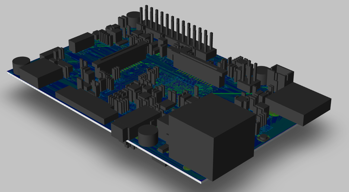
The Oz64 3D model
RISC-V.png

The Oz64 is a low cost single-board computer based on the Sophgo SG2000 SoC with dual T-Head C906 64-bit RISC-V cores, an ARM Cortex A53 64-bit RISC CPU core and an 8051 8-bit core supported by 512 MB of embedded DRAM memory, with WiFi and Bluetooh radio interfaces. The Oz64 SBC comes in a model-B form-factor, has a microSD card slot, an eMMC plugin connector, an USB 2.0 Type-A host port, and many other peripheral interfaces for makers to integrate with sensors and other devices.

Software Releases

Quick Links to the Source of OS Images Build

There is a community effort to bring updated kernels, peripherals and buildroot - Lots of communication happening in the #ox64-nutcracker channel.

Toolchain:

  • elf_newlib_toolchain/bin/riscv64-unknown-elf-gcc (Xuantie-900 elf newlib gcc Toolchain V2.2.5 B-20220323) 10.2.0
  • linux_toolchain/bin/riscv64-unknown-linux-gnu-gcc (Xuantie-900 linux-5.10.4 glibc gcc Toolchain V2.2.4 B-20211227) 10.2.0
  • cmake version 3.19.3

Software Development Kits

SoC and Memory Specification

Sophgo-icon.jpg

Based on the Sophgo SG-200x

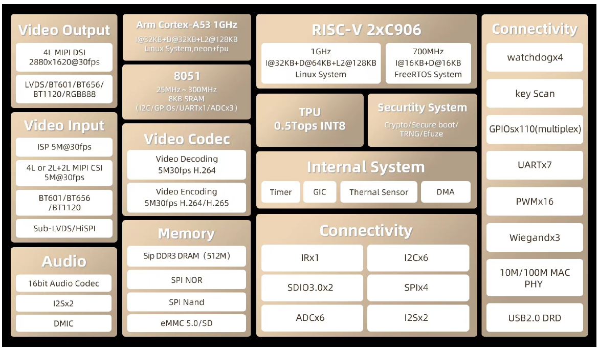
SG2000 Block Diagram.png

CPU Architecture

T-Head.png

T-Head C906 1GHz MHz 64-bit RISC-V CPU:

  • Supports RISC-V RV64IMAFCV instruction architecture
  • Five-stage single-issue sequentially executed pipeline
  • Level-1 instruction and data cache of Harvard architecture, with a size of 32 KB and a cache line of 64KB
  • Level-2 128KB cache
  • Sv39 memory management unit, realizing the conversion of virtual and real addresses and memory management
  • jTLB that supports 128 entries
  • Supports AXI 4.0 128-bit master interface
  • Supports core local interrupt (CLINT) and platform-level interrupt controller (PLIC)
  • With 80 external interrupt sources, 3 bits for configuring interrupt priority
  • Supports BHT (8K) and BTB
  • Compatible with RISC-V PMP, 8 configurable areas
  • Supports hardware performance monitor (HPM) units
  • See here

T-Head C906 700Mhz MHz 64-bit RISC-V CPU:

  • Supports RISC-V RV64IMAFCV instruction architecture
  • Five-stage single-issue sequentially executed pipeline
  • Level-1 instruction and data cache of Harvard architecture, with a size of 16 KB and a cache line of 16KB
  • Sv39 memory management unit, realizing the conversion of virtual and real addresses and memory management
  • jTLB that supports 128 entries
  • Supports AXI 4.0 128-bit master interface
  • Supports core local interrupt (CLINT) and platform-level interrupt controller (PLIC)
  • With 80 external interrupt sources, 3 bits for configuring interrupt priority
  • Supports BHT (8K) and BTB
  • Compatible with RISC-V PMP, 8 configurable areas
  • Supports hardware performance monitor (HPM) units
  • See here
Arm-logo.png

ARM Cortex-A53 1GHz 64-bit RISC CPU:

  • Quad-core Cortex-A53 up to 1.0GHz CPU
  • Full implementation of the ARM architecture v8-A instruction set
  • ARM Neon Advanced SIMD (single instruction, multiple data) support for accelerated media and signal processing computation
  • ARMv8 Cryptography Extensions
  • In-order pipeline with symmetric dual-issue of most instructions
  • Unified system L2 128KB cache
  • Includes VFP v3 hardware to support single and double-precision operations
  • Integrated 32KB L1 instruction cache, 32KB 4-way set associative L1 data cache
  • TrustZone technology support
  • PD_A53: Cortex-A53 + Neon + FPU + L1 I/D Cache of core 2/3


8051 25-300MHz 8-bit CPU:

  • Integrated 8K SRAM

System Memory

  • SIP DRAM 512MB

Board Features

Network

  • 2.4 GHz 1T1R WiFi6
  • Bluetooth 5.2
  • 10/100 Mbit/s Ethernet with optional PoE capability

Storage

  • On-board eMMC module socket
  • MicroSD, supports SDHC and SDXC

Expansion Ports

  • USB 2.0 Host port
  • 26 GPIO pins, including SPI, I2C and UART functionality
  • 2x Dual-lane MiPi CSI port
  • Optional dual-lane MiPi DSI port

Board Information, Schematics and Certifications

Board Dimensions: 85mm x 56mm x 18.8mm, see the model-B board dimension drawing

Input Power: +5V @2A with 3.5mm/1.35mm Type H Barrel type DC connector (@1.5A will work if there is no heavy load on the USB 2.0 port)

Pre-Production version schematic:

Certifications:

  • Disclaimer: Please note that PINE64 SBC is not a "final" product and in general certification is not necessary.
  • Not yet available

Datasheets for Components and Peripherals

Sophgo SG2000 SoC information:

Wifi/BT information:

Power Regulator information:

MicroSD socket information:

Resources and Articles

Development Efforts

Build