Difference between revisions of "NASCase-STAR64"
(Adding PC fan adapter cable as alternative for fan connector modification) |
|||
| (2 intermediate revisions by the same user not shown) | |||
| Line 1: | Line 1: | ||
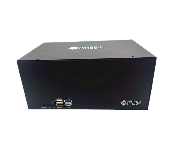
The PINE64 NAS Case is intended for either a Network Attached Storage (NAS) or Desktop application, but it can also be used in a number of other server capacities. It is built from precision-cut and powder-coated aluminum. The physical dimensions are 232.4 mm (Width) x 105.0 mm (Height) x 145.2 mm (Depth). | The PINE64 NAS Case is intended for either a Network Attached Storage (NAS) or Desktop application, but it can also be used in a number of other server capacities. It is built from precision-cut and powder-coated aluminum. The physical dimensions are 232.4 mm (Width) x 105.0 mm (Height) x 145.2 mm (Depth). | ||
| Line 46: | Line 44: | ||
*A PCIe to dual SATA adapter [https://forum.pine64.org/showthread.php?tid=6932 '''WARNING''': Old adapters with AS Media chips don't] [https://forum.pine64.org/showthread.php?tid=6511 work well with two HDD!] | *A PCIe to dual SATA adapter [https://forum.pine64.org/showthread.php?tid=6932 '''WARNING''': Old adapters with AS Media chips don't] [https://forum.pine64.org/showthread.php?tid=6511 work well with two HDD!] | ||
*One or two 2.5”/ 3.5” HDDs (not sold in the PINE store) | *One or two 2.5”/ 3.5” HDDs (not sold in the PINE store) | ||
*Medium heatsink (N.B. Any of the three available heatsinks will fit in the NAS Case but the medium one suites best for the NAS Case airflow) | |||
*eMMC module (The micro SD card slot is '''not''' accessible without modifying the case) | *eMMC module (The micro SD card slot is '''not''' accessible without modifying the case) | ||
*optionally an eMMC to USB 2.0 adapter | *optionally an eMMC to USB 2.0 adapter | ||
*80 mm fan with 12 V supply | *80 mm fan with 12 V supply | ||
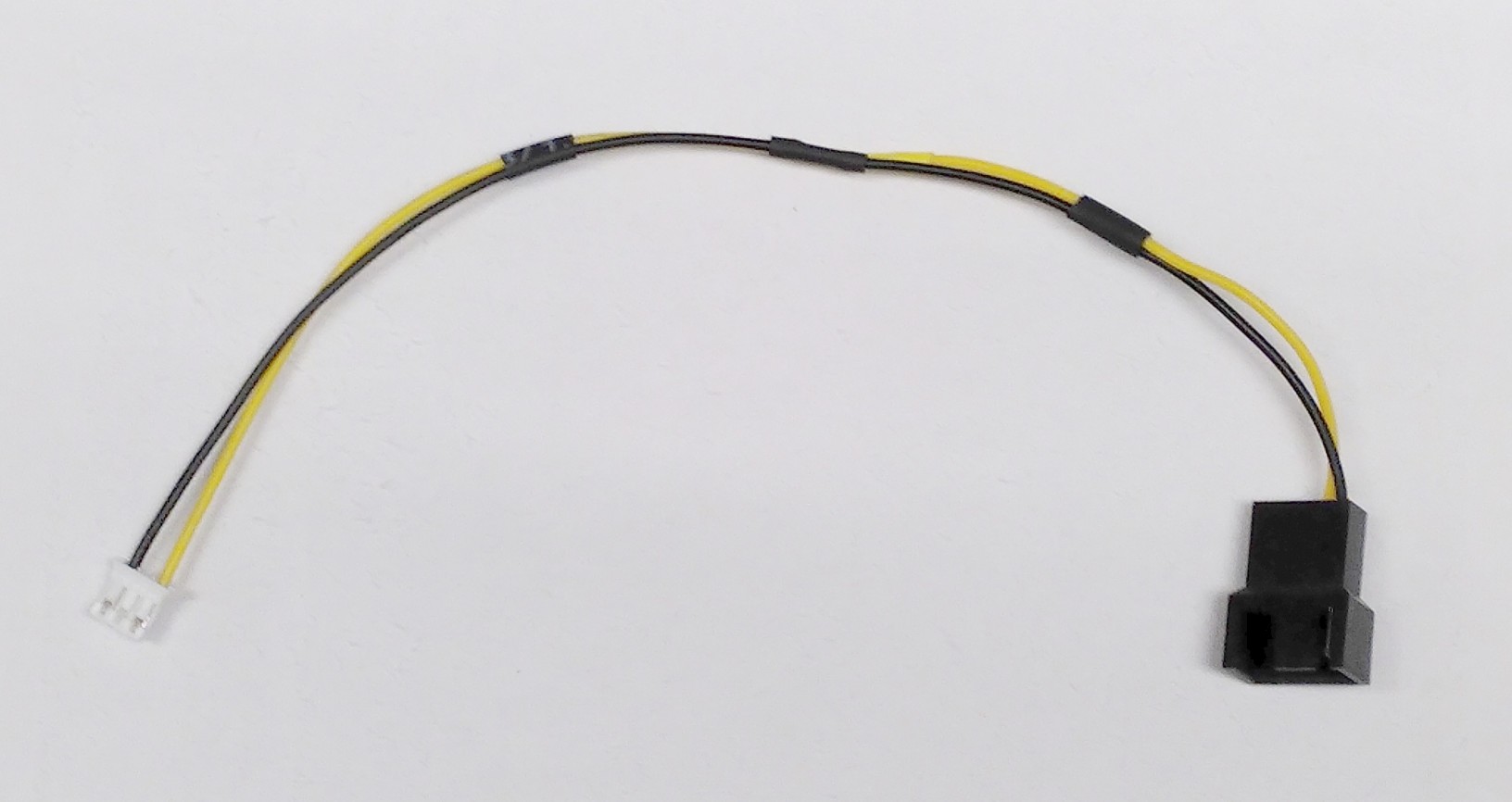
*3 pin JST PH connector and crimp contacts with 2 mm pitch (not sold in the PINE store) | *3 pin JST PH connector and crimp contacts with 2 mm pitch or a [https://www.tindie.com/products/brain4free/star64-fan-adapter-cable/ PC fan adapter cable] (not sold in the PINE store) | ||
==Which software should I use?== | ==Which software should I use?== | ||
| Line 76: | Line 75: | ||
You should now be left with a bare case ready for installation of the necessary components. | You should now be left with a bare case ready for installation of the necessary components. | ||
As the HDD power connector on the STAR64 revision 1.0 and 1.1 is reversed compared to the ROCKPro64 you have to modify the SATA power cable. Use a flat headed screw driver to push down the retention lever of the crimp contact and pull it out of the connector housing at the same time. Take your time, it's a bit fiddly and | As the HDD power connector (U26) on the STAR64 revision 1.0 and 1.1 is reversed compared to the ROCKPro64 you have to modify the SATA power cable. Use a flat headed screw driver to push down the retention lever of the crimp contact and pull it out of the connector housing at the same time. Take your time, it's a bit fiddly and if you use too much force you will damage the crimp contact and you will need to order replacements. | ||
First remove the two outer black and yellow pin, insert them again | First remove the two outer black and yellow pin, insert them again in the other position. Repeat with the two inner pins. Black and yellow cables are now swapped and ready for the STAR64. | ||
<div style="clear: both"></div> | <div style="clear: both"></div> | ||
| Line 104: | Line 103: | ||
===Step 4. Installing 80 mm Fan and eMMC=== | ===Step 4. Installing 80 mm Fan and eMMC=== | ||
[[File:STAR64-fan-parts.jpg|200px|thumb|left|The 80 mm fan and JST connector parts]] | [[File:STAR64-fan-parts.jpg|200px|thumb|left|The 80 mm fan and JST connector parts]] | ||
[[File:STAR64-fan-wiring.jpg|200px|thumb|right|Correct wiring of the fan cable]] | [[File:STAR64-fan-wiring.jpg|200px|thumb|right|Correct wiring of the fan cable to socket U25]] | ||
The eMMC is fitted into | [[File:Star64-fan-adapter-cable.jpg|200px|thumb|right|Alternatively use an adapter cable for 3 or 4 pin PC fans]] | ||
The eMMC is fitted into its respective placement on the STAR64 board - please consult the diagram for their correct installation. | |||
When you don't bought the PC fan adapter cable or using another 12 V fan then you have to mount the 3 pin, 2 mm pitch JST connector before mounting the fan into the NAS case. | |||
The fan should be mounted on the right-hand side of the case. We suggest that the fan is oriented for | The fan should be mounted on the right-hand side of the case. We suggest that the fan is oriented for positive pressure, blowing air into the case rather than taking air out. A positive pressure configuration both allows a filter to be placed over the intake to prevent dust ingress and the cage on the outlet side of the fan helps keep the wiring for 3.5" disks away from the fan blades. For best cable management results, have the fan power lead face the front of the case so that it can easily be routed to its header located next to GPIO pins on the STAR64. | ||
The fan should be secured using 4x long screws (that fasten into bolts) which can be found in the see-through bag supplied with the NAS Case. | The fan should be secured using 4x long screws (that fasten into bolts) which can be found in the see-through bag supplied with the NAS Case. | ||
Plug in the fan at this stage of the installation and route the cable at the bottom of the front of the case. | Plug in the fan at this stage of the installation (Socket U25) and route the cable at the bottom of the front of the case. | ||
<div style="clear: both"></div> | <div style="clear: both"></div> | ||
===Step 5. PCIe to SATA adapter and Cabling=== | ===Step 5. PCIe to SATA adapter and Cabling=== | ||
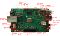
[[File: | [[File:Star64-map-connectors.svg|200px|thumb|left|U26 is the DC header on the STAR64 for the power cable]] | ||
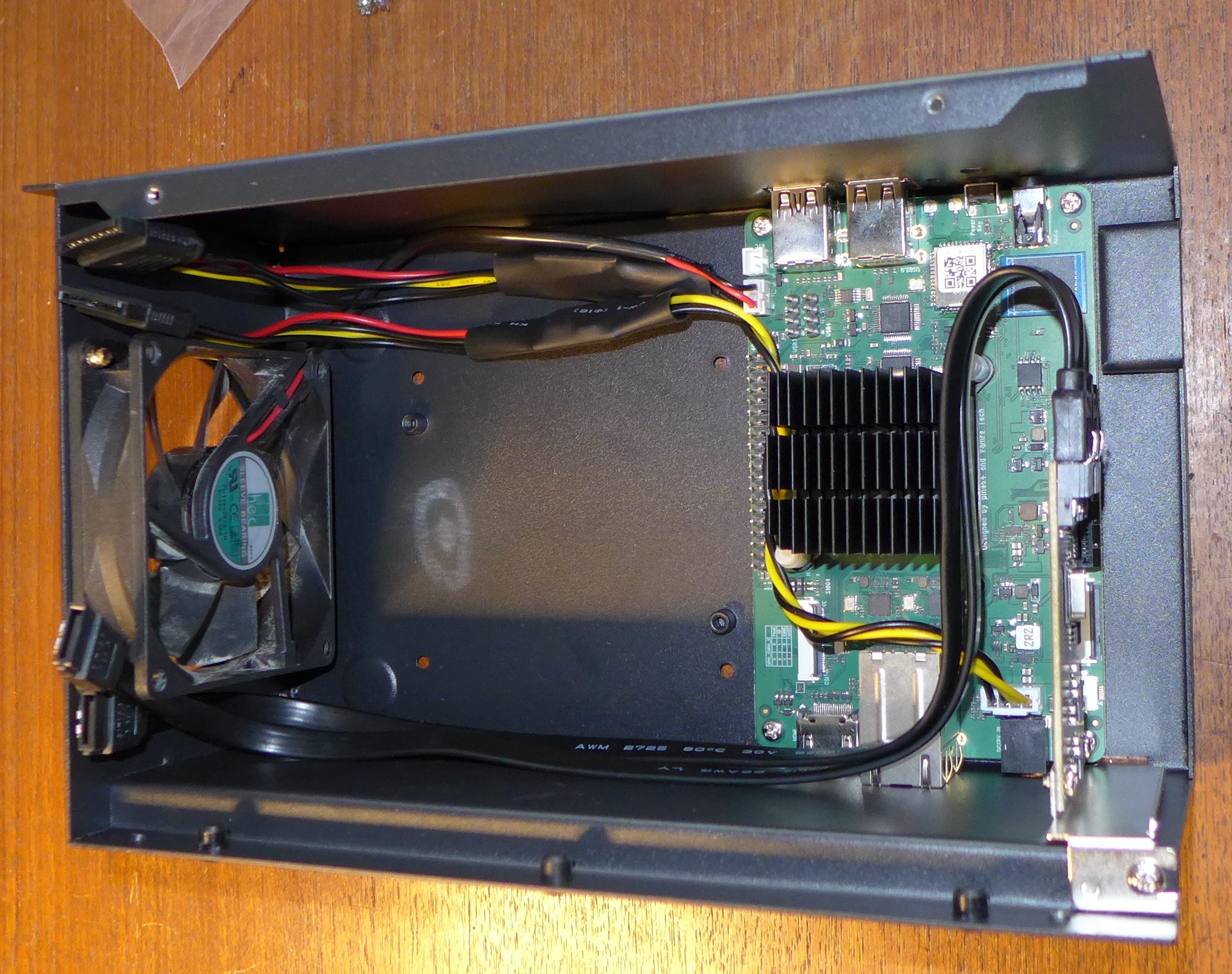
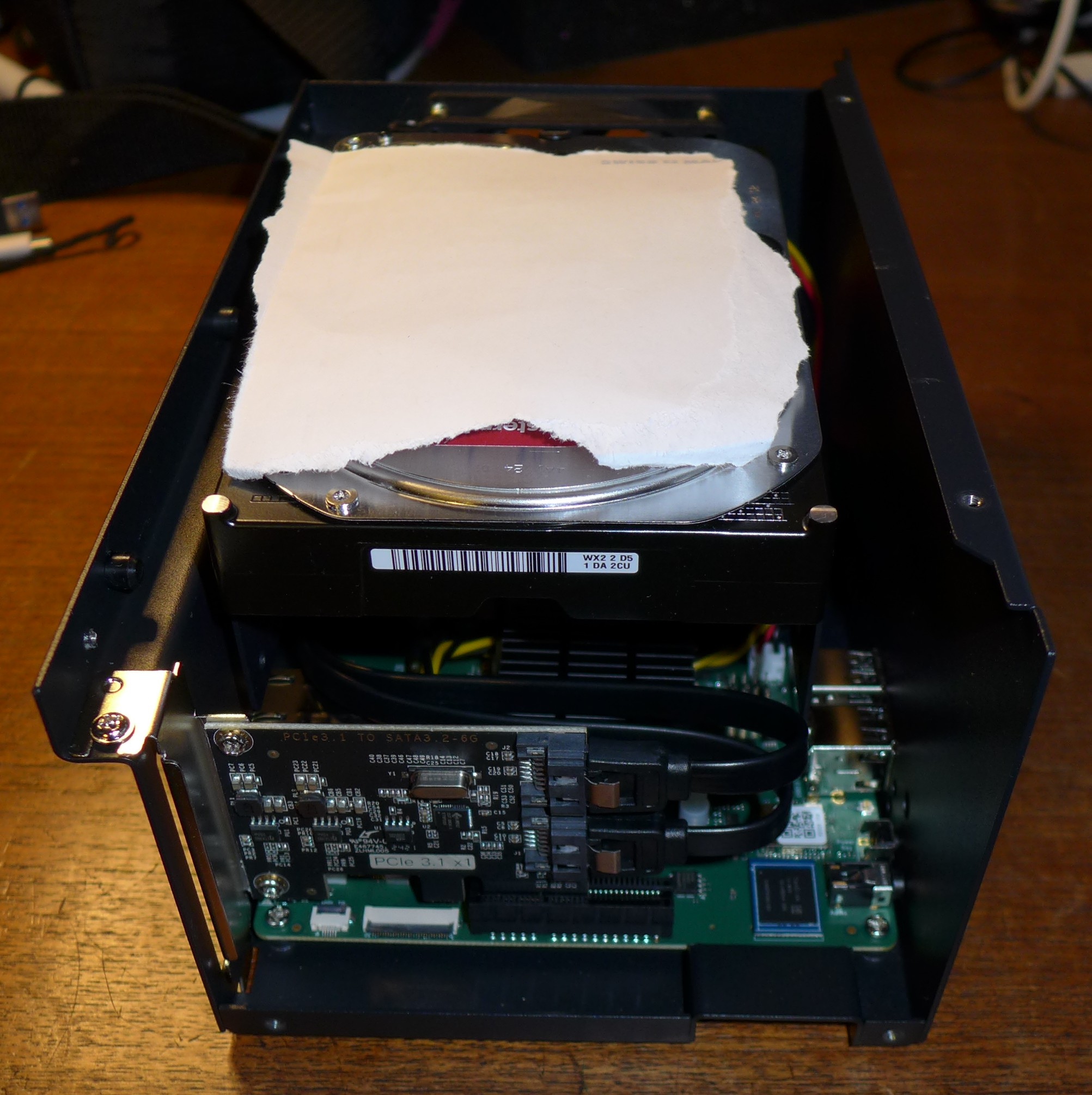
[[File:STAR64-NAS-internal-wiring.jpg|300px|thumb|right|PCIe to SATA installed and cables routed through the case]] | [[File:STAR64-NAS-internal-wiring.jpg|300px|thumb|right|PCIe to SATA installed and cables routed through the case]] | ||
With the board in place it's time to set up the PCIe to SATA adapter and do the cabling necessary to attach HDDs / SSDs. | With the board in place it's time to set up the PCIe to SATA adapter and do the cabling necessary to attach HDDs / SSDs. | ||
Latest revision as of 21:23, 2 November 2024
The PINE64 NAS Case is intended for either a Network Attached Storage (NAS) or Desktop application, but it can also be used in a number of other server capacities. It is built from precision-cut and powder-coated aluminum. The physical dimensions are 232.4 mm (Width) x 105.0 mm (Height) x 145.2 mm (Depth).
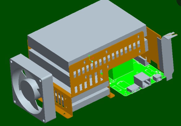
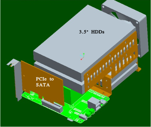
An exploded view of the NAS Case, illustrating how all the components come together, can be found here. Please refer back to this PDF document during assembly to verify correct orientation of individual components.
IO accessibility when the NAS Case is assembled
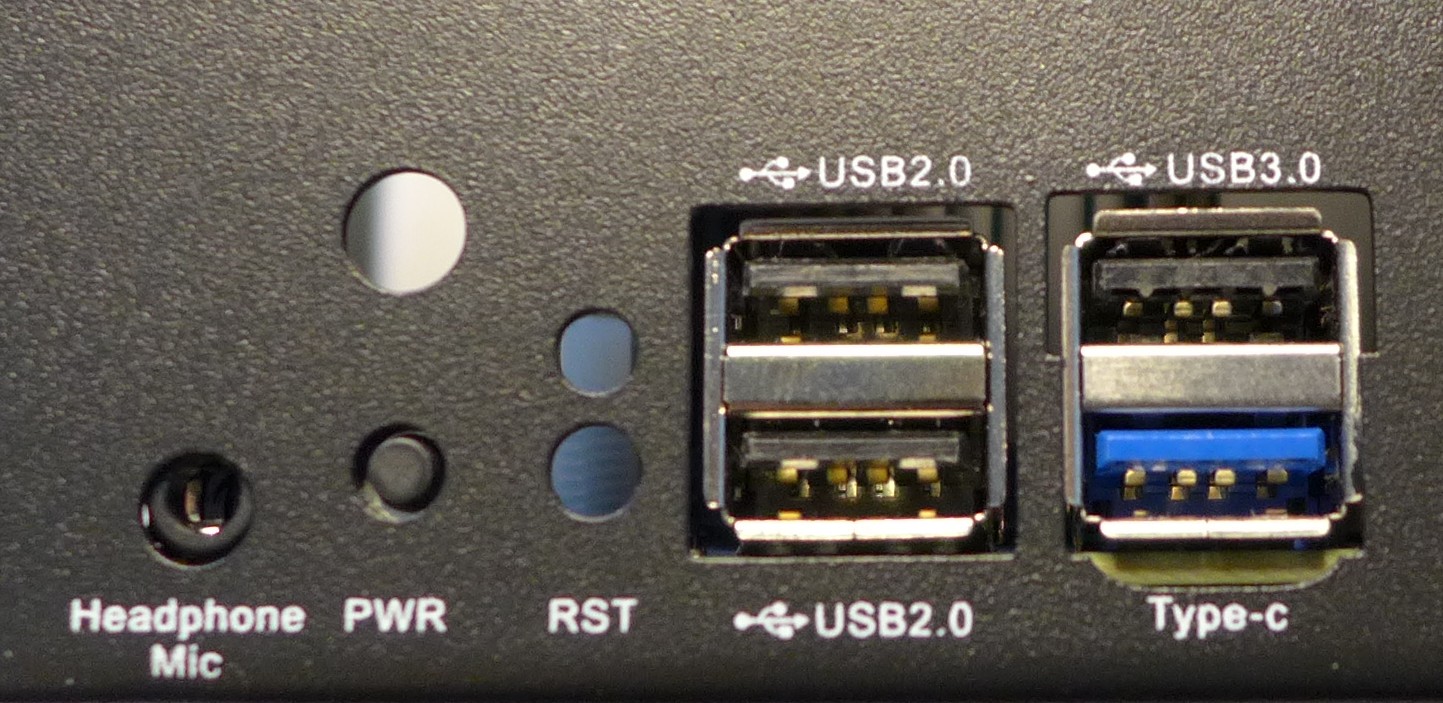
When the NAS Case is assembled and screwed shut these STAR64 IO ports remain accessible:
- Micro SD slot
- 3 x USB 2.0
- USB 3.0
- Power switch
- The headphone jack
- One Gigabit Ethernet port
- HDMI
Be aware that these STAR64 IO ports are not accessible without modifying the case:
- Micro SD slot
- Second Gigabit Ethernet port
What does the NAS Case house?
The NAS Case can house the following components:
- A STAR64 Single Board Computer (SBC) with a tall, mid-size or slim heatsink
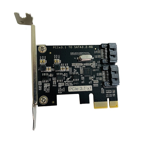
- A PCIe to dual SATA adapter or a different low-profile PCIe card, e.g. an NVMe adapter
- Either two 3.5” OR two 2.5” HDDs / SSDs; combination of any two sized drives is accepted
- A 80 mm fan with 12 V supply voltage
- Up to three SMA antennas, two of which can be attached to the WiFi/ BT module
What comes in the box?
When you purchase the NAS Case from the PINE store the following items are shipped to you:
- The NAS Case itself, which consists of a top and a bottom half as well as an internal HDD SSD mount.
- Two SATA cables
- A custom power cable capable of powering two 2.5” or 3.5” HDDs /SSDs
- The required screws, fittings and a LED relay
What other bare-minimum things do I need for a NAS build?
To assemble a functional NAS in the NAS Case you will require a number of additional parts. With the exception of HDDs/SSDs, most of it can be purchased from the PINE64 store:
- A STAR64 4 GiB or 8 GiB board
- A 12 V 5 A power supply
- A PCIe to dual SATA adapter WARNING: Old adapters with AS Media chips don't work well with two HDD!
- One or two 2.5”/ 3.5” HDDs (not sold in the PINE store)
- Medium heatsink (N.B. Any of the three available heatsinks will fit in the NAS Case but the medium one suites best for the NAS Case airflow)
- eMMC module (The micro SD card slot is not accessible without modifying the case)
- optionally an eMMC to USB 2.0 adapter
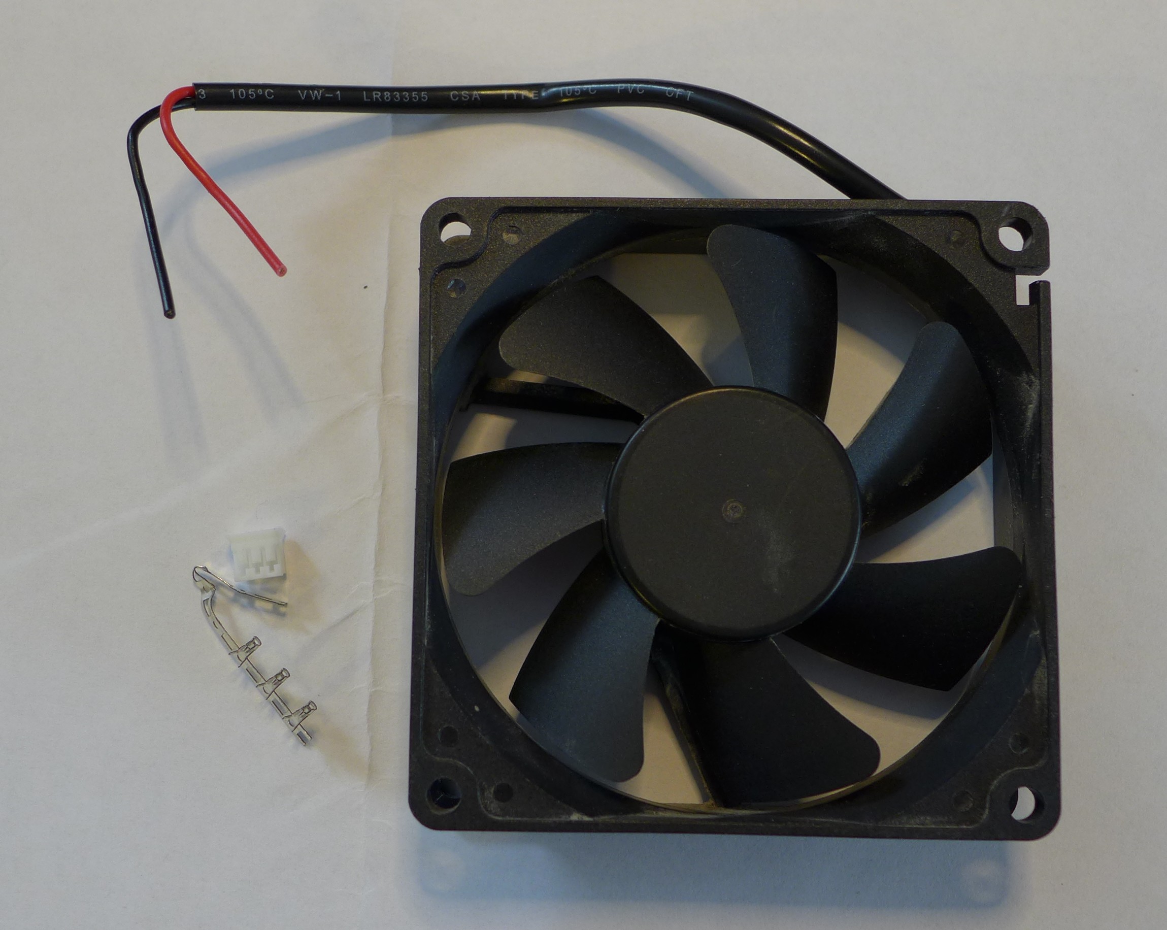
- 80 mm fan with 12 V supply
- 3 pin JST PH connector and crimp contacts with 2 mm pitch or a PC fan adapter cable (not sold in the PINE store)
Which software should I use?
Help needed!
Follow First Setup to install an operating system and test if it boots.
Please help to contribute with your experience:
- OMV for Risc-V?
- Nextcloud?
- Others?
Step-by-Step Assembly Instructions
If you want an overview of the process before you start in video format check out this instructional video for the ROCKPro64.
Come back afterwards and read the instructions carefully here, as there are few important differences when using a STAR64!
Step 1. Preparation of the NAS Case for Installation
Remove the top of the NAS Case. It is held together by two screws on either side with the exception of the bottom (left, right, top and back). Once done, the top of the case should lift right off without any resistance.
The next step is to remove the HDD/SSD holding bracket, which is screwed into the bottom of the case. Flip the bottom over and undo the screws which hold the bracket in place.
You should now be left with a bare case ready for installation of the necessary components.
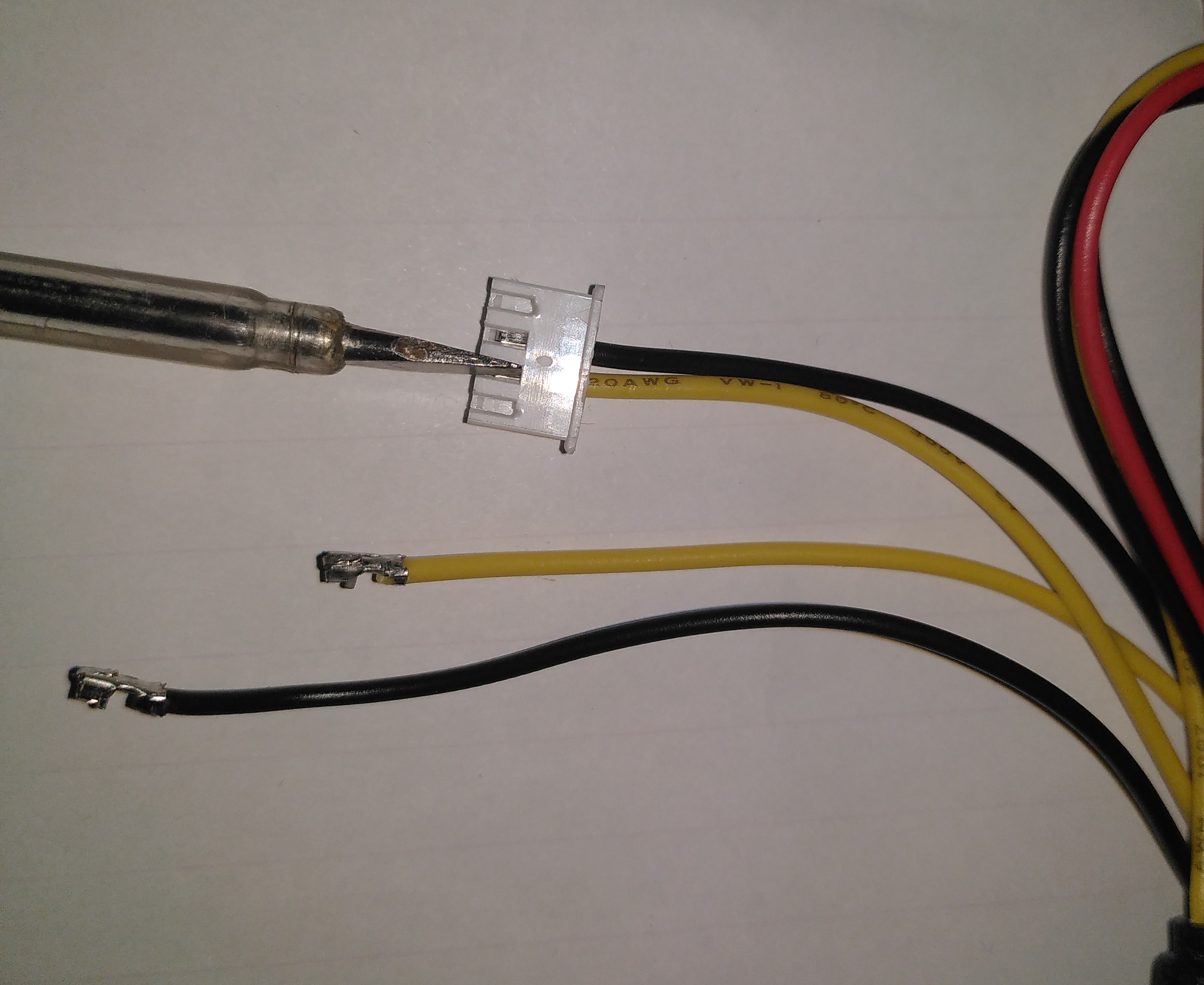
As the HDD power connector (U26) on the STAR64 revision 1.0 and 1.1 is reversed compared to the ROCKPro64 you have to modify the SATA power cable. Use a flat headed screw driver to push down the retention lever of the crimp contact and pull it out of the connector housing at the same time. Take your time, it's a bit fiddly and if you use too much force you will damage the crimp contact and you will need to order replacements.
First remove the two outer black and yellow pin, insert them again in the other position. Repeat with the two inner pins. Black and yellow cables are now swapped and ready for the STAR64.
Step 2. Install operating system
The micro SD card slot is not accessible from outside. Therefore you have to install the chosen operating system before mounting the STAR64 into the NAS case when using an micro SD card for the installation process.
Alternative is that you have the optional eMMC to USB 2.0 adapter to install the operating system then you can do it just before step 6 (or now and test if everything is working).
Test that your STAR64 boots from eMMC before installing it in the case as the DIP switch to select the boot mode is below the HDD cage and is not reachable without partial disassembly.
Step 3. Installing the STAR64 into the NAS Case
Make sure nothing is plugged into your STAR64 - including antennas and micro SD card.
If you intend to use a heatsink with your board then please install it now before proceeding. If you bought the heatsink from the Pine64 store it comes with thermal paste and/or a thermal pad. You can use one or the other (not both!). The thermal pad is easier to apply but the thermal paste should be better at cooling if properly applied.
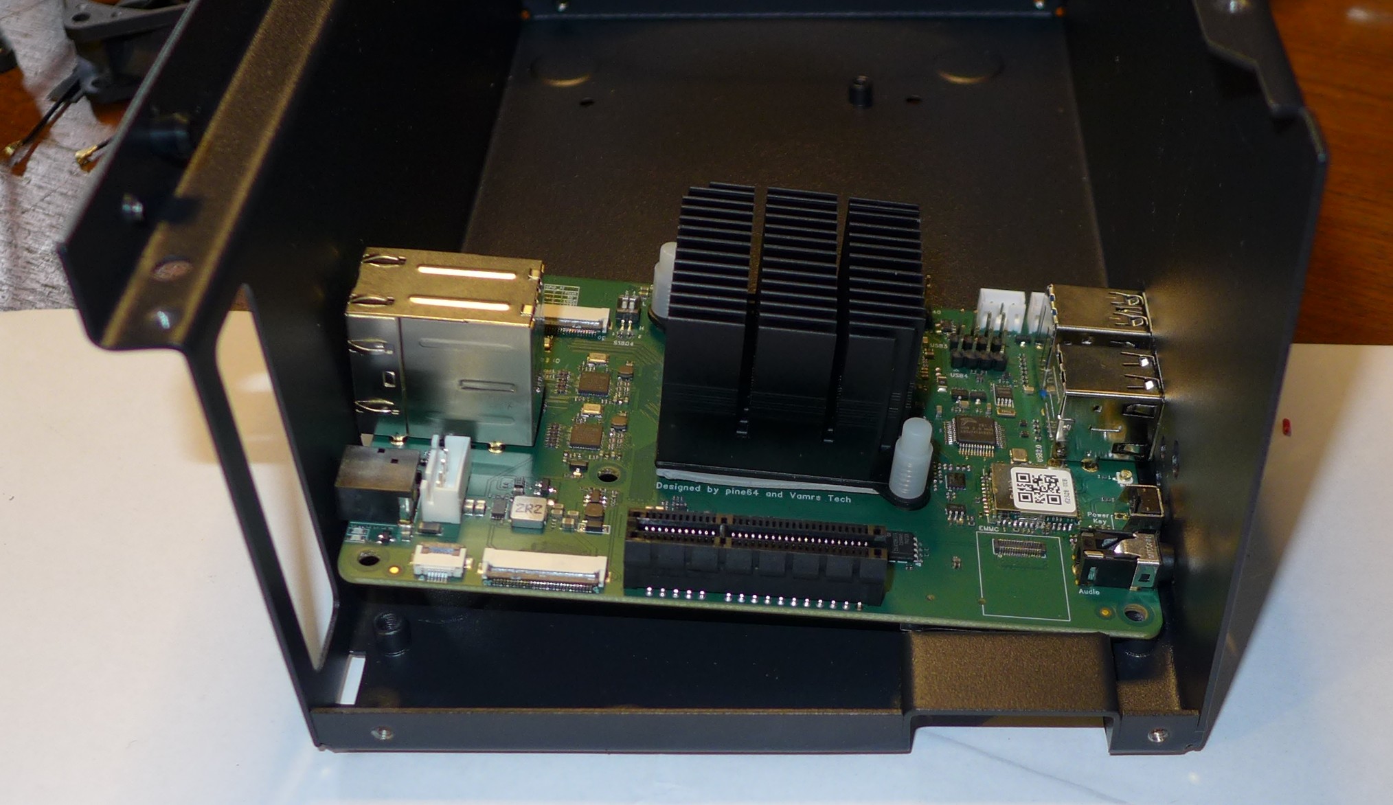
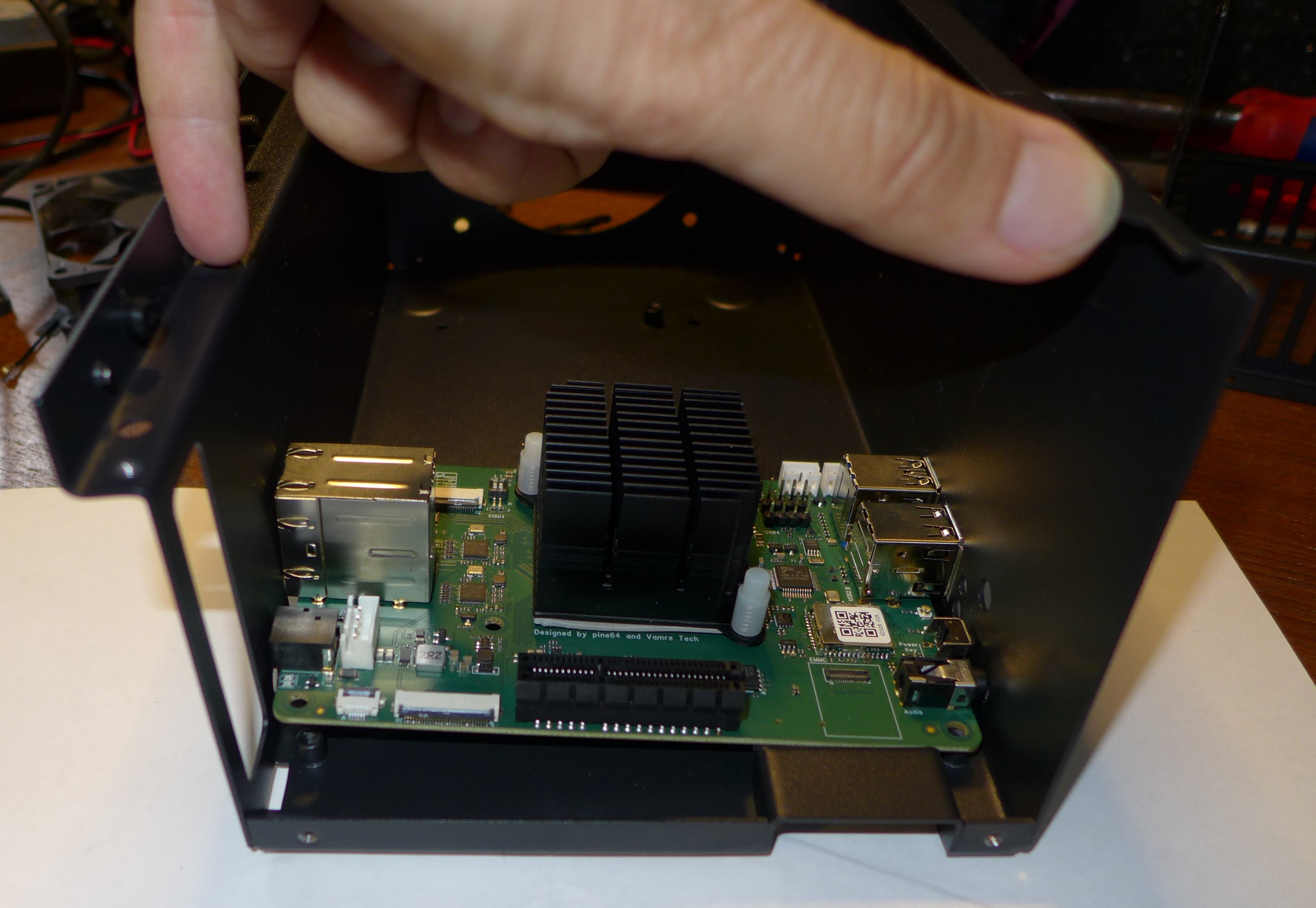
Place your STAR64 into the case with USB 2.0 and 3.0 ports facing the front of the case. Install it by placing it with the USB connectors and power button first with a slight angle into the case. Then push gently the side walls of the NAS case outwards until the STAR64 falls into place.
Secure the board with 4x screws included in the see-through bag. Make sure that the board is held firmly in the case but do not overtighten the screws.
On the STAR64 the LEDs are at the back so just ignore the small semi-opaque plastic cylinder you can find in the see-through bag.
Step 4. Installing 80 mm Fan and eMMC
The eMMC is fitted into its respective placement on the STAR64 board - please consult the diagram for their correct installation.
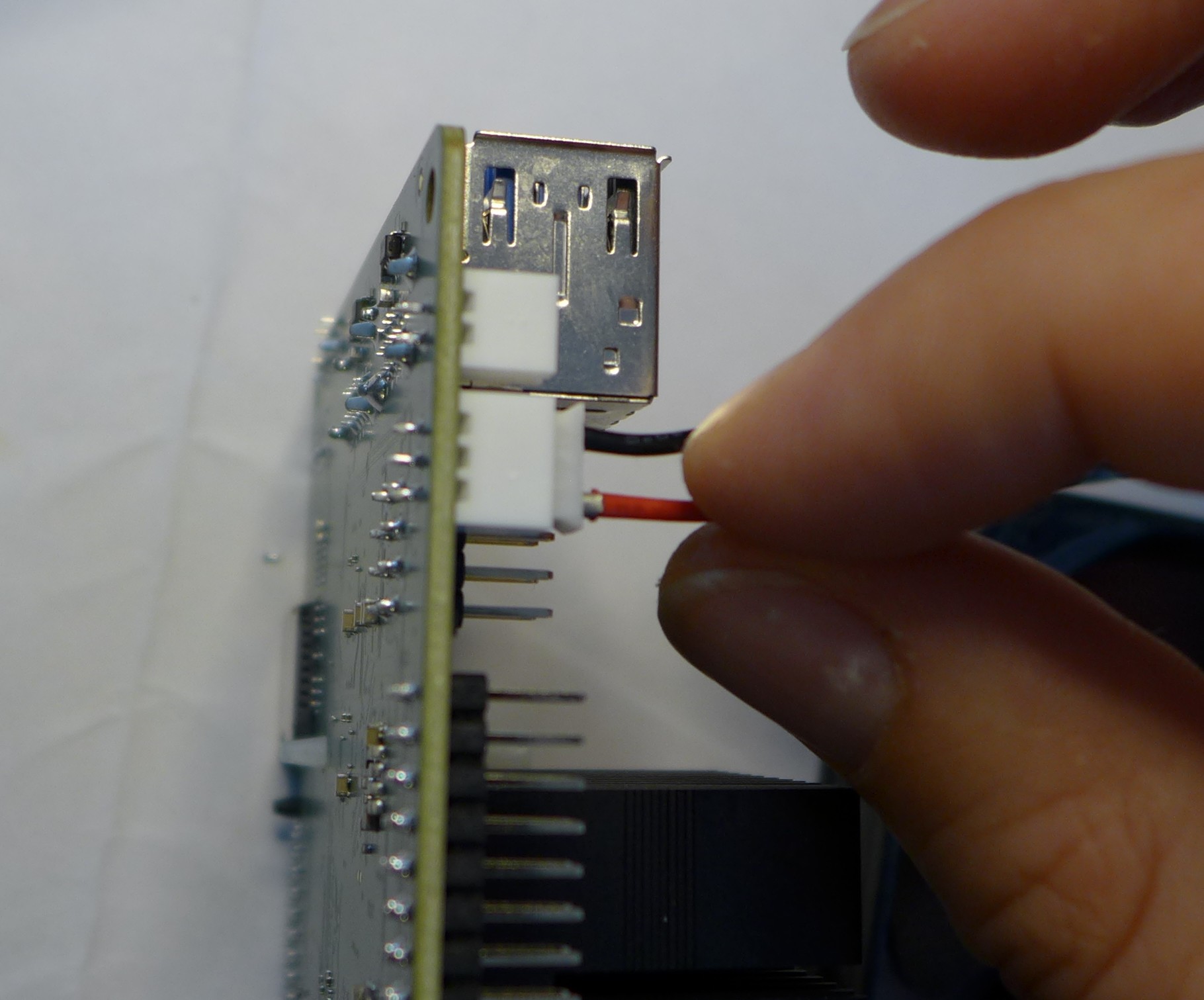
When you don't bought the PC fan adapter cable or using another 12 V fan then you have to mount the 3 pin, 2 mm pitch JST connector before mounting the fan into the NAS case.
The fan should be mounted on the right-hand side of the case. We suggest that the fan is oriented for positive pressure, blowing air into the case rather than taking air out. A positive pressure configuration both allows a filter to be placed over the intake to prevent dust ingress and the cage on the outlet side of the fan helps keep the wiring for 3.5" disks away from the fan blades. For best cable management results, have the fan power lead face the front of the case so that it can easily be routed to its header located next to GPIO pins on the STAR64. The fan should be secured using 4x long screws (that fasten into bolts) which can be found in the see-through bag supplied with the NAS Case. Plug in the fan at this stage of the installation (Socket U25) and route the cable at the bottom of the front of the case.
Step 5. PCIe to SATA adapter and Cabling
With the board in place it's time to set up the PCIe to SATA adapter and do the cabling necessary to attach HDDs / SSDs.
Place the SATA Adapter into the PCIe slot on the STAR64 board so that the holding bracket of the adapter faces the back of the case. In the back of the case there is a cutout for the PCIe adapter.
Secure the PCIe dual SATA Adapter with a single screw at the top of the bracket, in the back of the NAS Case.
This is the right time to plug in the SATA and custom power cable. The SATA cables plug into the ports on the top or front of the adapter while the power cable plugs into DC header located on the board - just below the power jack, to the left of the Ethernet port (when viewed from front).
Have the cables hang outside the case or to the side for now so that they do not get in the way until they are needed.
Step 6. Installing HDDs / SSDs into the Holding Bracket
The next step is to install HDDs/ SSDs into their holding bracket; 2.5” drives need to be installed at the very bottom of the bracket while 3.5” drives are at the top of the the bracket.
For 2.5” drives make sure that the drives are oriented up and their SATA and power ports face the front of the NAS Case.
For 3.5” HDDs, make sure they are oriented up and their SATA and power ports face the right side of the NAS Case (towards the fan mounting location).
Each drive you mount in the holding bracket requires 4x screws which come supplied in the see-through bag. Make sure the drives are held in place firmly but do not over-tighten the screws.
Once the holding bracket is assembled and you have your drives mounted, please set it aside and proceed to the next step.
Step 7. Installing Extras (SMA Antennas)
If you have additional peripherals, such as an SMA Antennas, then now is the right time to install them. If you have none of the above, please proceed to step 8 of this guide.
If you intend to use external u.FL to SMA antennas in the NAS Case then this is also the time to install them into the case. In the back section of the case at the very top you will find three cut-outs where the SMA antennas can be fitted. Don’t plug the u.FL leads antenna leads into the WiFi/BT module just yet - instead wait until after the disk holding bracket is installed into the case (step 6).
Step 8. Installing the HDD / SSD Bracket and Routing Cables
Installing the HDD/SSD bracket into the case and wiring it up is the last step before closing up the case.
Place the bracket with the disks installed (from step 4) into the case. The bracket should line up with the guiding bolts and screw holes at the bottom of the case. The section of the bracket that holds 3.5” HDDs needs to face the left side of the case (when viewed from front) and should overhang the STAR64 board slightly. The 3.5” SATA and power ports should face the right side of the case - where the fan mounts, while 2.5” SATA and power ports should face the front of the case.
With the bracket aligned, flip the bottom of the case over while holding the bracket in place. Screw it into place using 4x Phillips head screws that came included with the NAS Case.
The last thing remaining before the NAS Case can be screwed shut is routing SATA and power cables: For 3.5” HDDs we suggest routing power and SATA cables underneath the drives, where 2.5” HDDs/SSDs would otherwise reside.
For 2.5” disks you have plenty of routing options as there is much space available. The most obvious route is straight over the disks, where the 3.5” HDDs would reside.
Step 9. Closing the NAS Case and Powering On your NAS
Almost there. All that's left to do is to screw together the NAS Case. Screw in the top front screws first followed by screws on either side of the case. Do the back screws last. There, you are done.
To power on your new NAS Case and HDDs all you need to do is to plug in power and Ethernet (This is obviously assuming that you are intending to use it as a NAS or a headless server).
