Difference between revisions of "File:UART-pinecil-breakout-board-testing30.png"
Jump to navigation
Jump to search
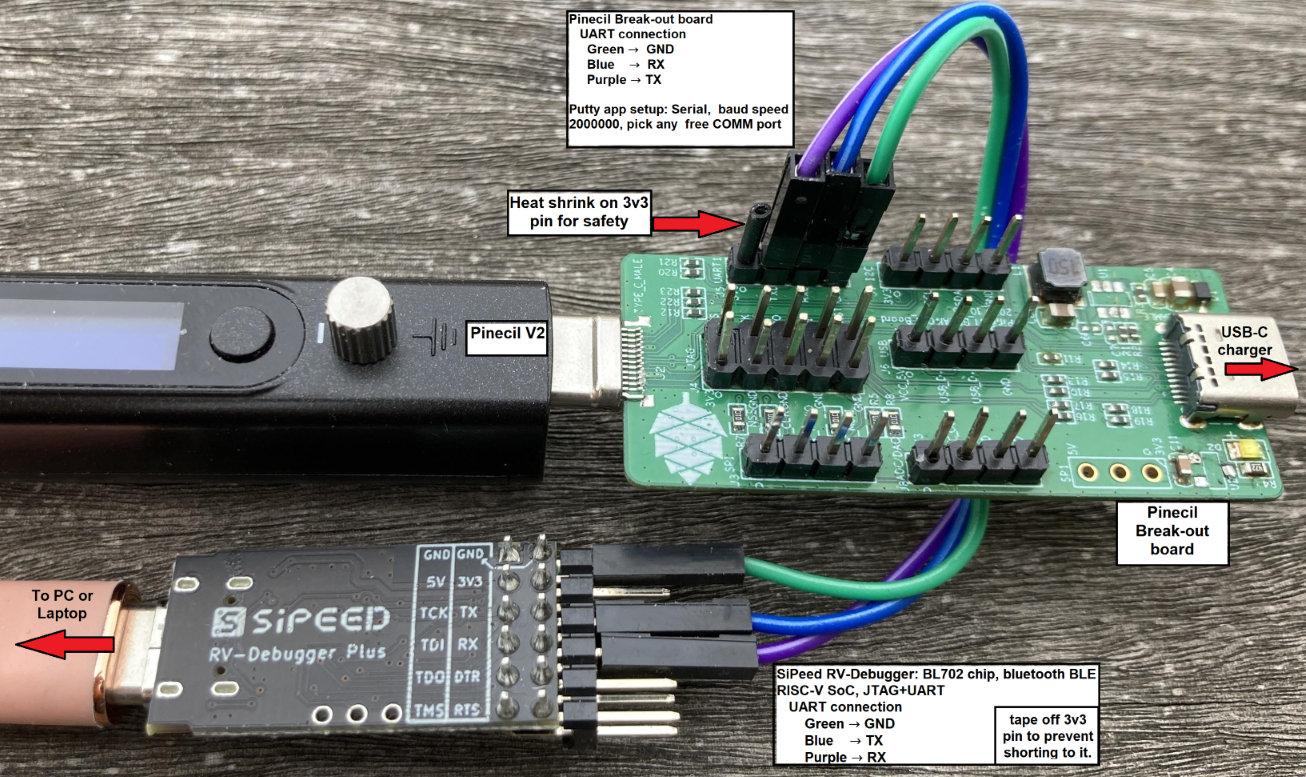
(Pinecil Break-out board for debugging and dev. - attach to any UART ttl converter. - example here with Sipeed RV-debugger-plus JTAG+UART BL702, a full-featured open source support for secondary development - Github repo for [SiPeed device](https://github.com/sipeed/RV-Debugger-BL702) Category: Pinecil) |
m (→Summary) |
||
| (6 intermediate revisions by the same user not shown) | |||
| Line 1: | Line 1: | ||
== Summary == | == Summary == | ||
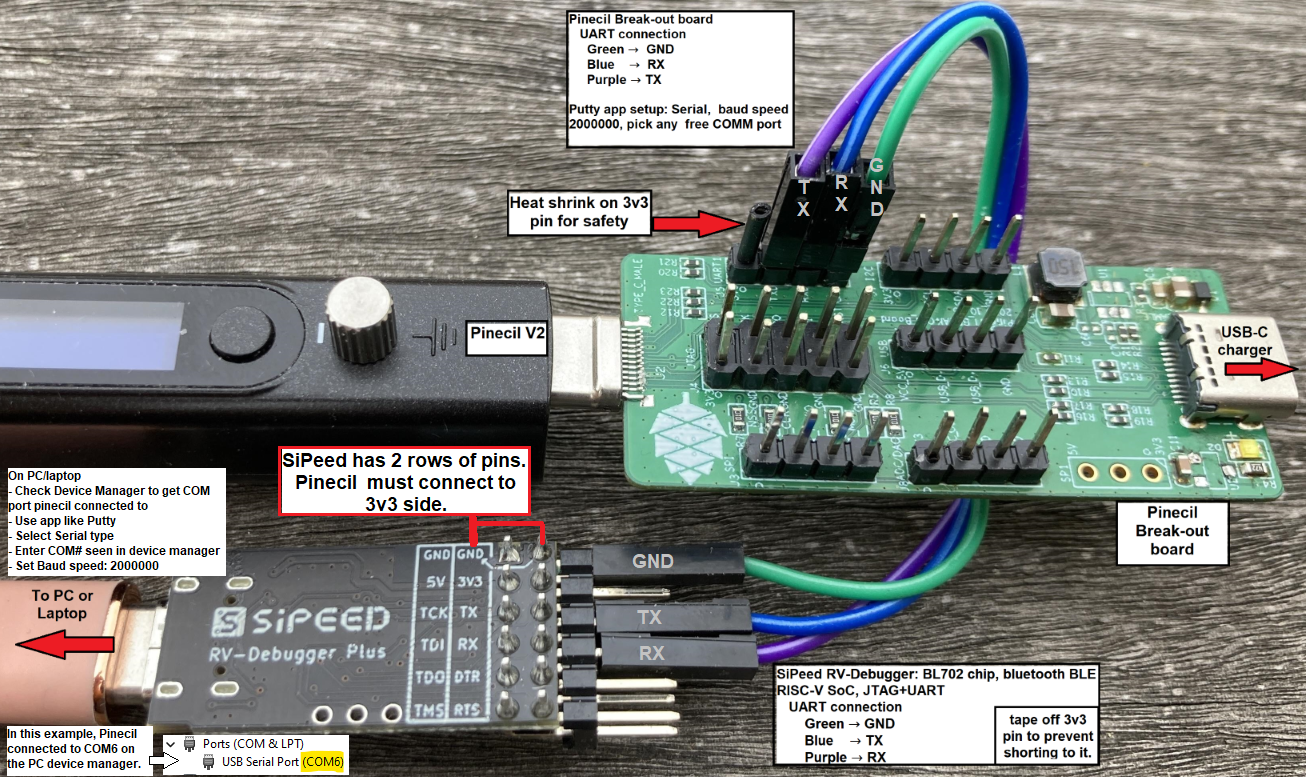
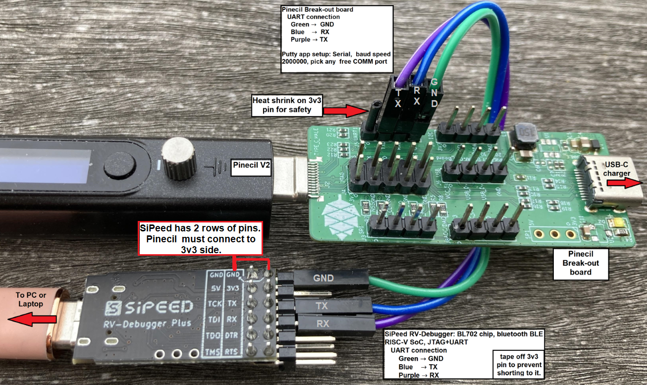
Pinecil Break-out board for debugging and dev. | Pinecil Break-out board for debugging and dev. (these directions are for the V2 model of Pinecil). | ||
- | * attach wires from the Break-out board to any UART TTL converter (siPeed in this photo). | ||
- example here | * reverse the RX and TX when connecting so that Rx --> TX and TX --> RX between the Breakout board and the UART adapter. | ||
* connect a USB-C cable from the SiPeed adapter to a PC/laptop. | |||
* Open Device manager or simlilar to check which COM port the Pinecil V2 connected to. | |||
* Open an app like Putty, select Serial type, set baud speed to 2000000, and enter the same COM number retrieved from Device Manager. | |||
* example here is the Sipeed RV-debugger-plus JTAG+UART BL702, which has full-featured open source support for secondary development | |||
* SiPeed: although not needed for UART testing, the full Github repo for the [https://github.com/sipeed/RV-Debugger-BL702 SiPeed device is here] and has other functions. | |||
[[Category: Pinecil]] | [[Category: Pinecil]] | ||
Latest revision as of 22:05, 10 April 2023
Summary
Pinecil Break-out board for debugging and dev. (these directions are for the V2 model of Pinecil).
- attach wires from the Break-out board to any UART TTL converter (siPeed in this photo).
- reverse the RX and TX when connecting so that Rx --> TX and TX --> RX between the Breakout board and the UART adapter.
- connect a USB-C cable from the SiPeed adapter to a PC/laptop.
- Open Device manager or simlilar to check which COM port the Pinecil V2 connected to.
- Open an app like Putty, select Serial type, set baud speed to 2000000, and enter the same COM number retrieved from Device Manager.
- example here is the Sipeed RV-debugger-plus JTAG+UART BL702, which has full-featured open source support for secondary development
- SiPeed: although not needed for UART testing, the full Github repo for the SiPeed device is here and has other functions.
File history
Click on a date/time to view the file as it appeared at that time.
| Date/Time | Thumbnail | Dimensions | User | Comment | |
|---|---|---|---|---|---|
| current | 21:37, 10 April 2023 |  | 1,306 × 777 (1.6 MB) | River (talk | contribs) | includ Baud speed |
| 01:54, 7 April 2023 |  | 1,306 × 777 (1.63 MB) | River (talk | contribs) | ||
| 01:11, 7 April 2023 |  | 1,306 × 777 (1.64 MB) | River (talk | contribs) | Pinecil Break-out board for debugging and dev. - attach to any UART ttl converter. - example here with Sipeed RV-debugger-plus JTAG+UART BL702, a full-featured open source support for secondary development - Github repo for [SiPeed device](https://github.com/sipeed/RV-Debugger-BL702) Category: Pinecil |
You cannot overwrite this file.
File usage
The following page uses this file: