Difference between revisions of "SOQuartz"
| (46 intermediate revisions by 8 users not shown) | |||
| Line 19: | Line 19: | ||
* Integrated 32KB L1 instruction cache and 32KB L1 data cache per core | * Integrated 32KB L1 instruction cache and 32KB L1 data cache per core | ||
* 512KB unified system L3 cache | * 512KB unified system L3 cache | ||
=== GPU (Graphics Processing Unit) Capabilities === | === GPU (Graphics Processing Unit) Capabilities === | ||
| Line 35: | Line 34: | ||
* Supports integer 8 and integer 16 convolution operations | * Supports integer 8 and integer 16 convolution operations | ||
* Supports the following deep learning frameworks: TensorFlow, TF-lite, Pytorch, Caffe, ONNX, MXNet, Keras, Darknet | * Supports the following deep learning frameworks: TensorFlow, TF-lite, Pytorch, Caffe, ONNX, MXNet, Keras, Darknet | ||
=== System Memory === | === System Memory === | ||
* RAM Memory Variants: 2GB, 4GB, 8GB LPDDR4. | * RAM Memory Variants: 2GB, 4GB, 8GB LPDDR4. | ||
* Storage Memory: optional 128Mb SPI Flash and optional eMMC module from | * Storage Memory: optional 128Mb SPI Flash and optional eMMC module from 8GB up to 128GB | ||
=== Network === | === Network === | ||
* 10/100/1000Mbps Ethernet | * 10/100/1000Mbps Ethernet | ||
* WiFi 802.11 b/g/n/ac with Bluetooth 5.0 | * WiFi 802.11 b/g/n/ac with Bluetooth 5.0 | ||
== SOQuartz exposed peripherals == | |||
=== Displays / Cameras === | |||
* 1x HDMI | |||
* 2x DSI | |||
* 1x eDP (Instead of HDMI1) | |||
* 1x LVDS (not available when dual-mode DSI) | |||
* 1x CSI 4-line | |||
=== Connectivity === | |||
* 1x Ethernet (1Gbit) | |||
* 1x USB 2.0 OTG | |||
* 1x SD Card (SD) | |||
* 1x PCIe 1-Line | |||
* 28x GPIO (TBD) | |||
== Connector Pins Definition == | |||
* [https://files.pine64.org/doc/quartz64/SOQuartz%20Connector%20Pin%20Assignments%20ver%201.0.ods SOQuartz Module Connector Pins Definition ver 1.0] | |||
== SOQuartz Model-A Baseboard Features == | == SOQuartz Model-A Baseboard Features == | ||
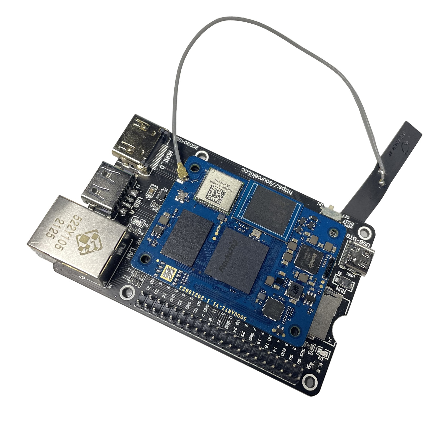
[[File:SOQuartz_model-A_baseboard.jpg |400px|thumb|SOQuartz Model-A Baseboard]] | |||
* Model "A" Baseboard Dimensions: 133mm x 80mm x 19mm | * Model "A" Baseboard Dimensions: 133mm x 80mm x 19mm | ||
* Input Power: DC 12V @ 3A 5.5OD/2.1ID Barrel DC Jack connector | * Input Power: DC 12V @ 3A 5.5OD/2.1ID (IEC 60130-10 Type A) Barrel DC Jack connector | ||
=== Storage === | === Storage === | ||
* microSD - bootable, support SDHC and SDXC, storage up to | * microSD - bootable, support SDHC and SDXC, storage up to 2TB | ||
* USB - 2 USB2.0 Host port | * USB - 2 USB2.0 Host port | ||
| Line 61: | Line 80: | ||
* 2x20 pins "Pi2" GPIO Header | * 2x20 pins "Pi2" GPIO Header | ||
* PCIe 1x open ended slot | * PCIe 1x open ended slot | ||
* 1x5 pin USB Expansion Header (J15) | |||
=== GPIO Pins === | |||
Attention! GPIOs are 3.3V! | |||
Interesting alternate pin configurations are listed in [brackets]. | |||
{| class="wikitable plainrowheaders" border="1" | |||
! scope="col" style="width:20em;" | Assigned To | |||
! scope="col" | Pin no. | |||
! scope="col" | Pin no. | |||
! scope="col" style="width:20em;" | Assigned To | |||
|- | |||
| style="text-align:right;"| 3.3 V | |||
| style="text-align:center; background-color:yellow; color:black; font-weight:bold;"| 1 | |||
| style="text-align:center; background-color:red; color:gold; font-weight:bold;"| 2 | |||
| style="text-align:left;"| 5 V | |||
|- | |||
| style="text-align:right;"| ''[I2C2_SDA_M1]'' GPIO4_B4_3V3 <sup style="font-style:italic;color:green">a</sup> | |||
| style="text-align:center; background-color:green; color:gold; font-weight:bold;"| 3 | |||
| style="text-align:center; background-color:red; color:gold; font-weight:bold;"| 4 | |||
| style="text-align:left;"| 5 V | |||
|- | |||
| style="text-align:right;"| ''[I2C2_SCL_M1]'' GPIO4_B5_3V3 <sup style="font-style:italic;color:green">a</sup> | |||
| style="text-align:center; background-color:green; color:gold; font-weight:bold;"| 5 | |||
| style="text-align:center; background-color:black; color:gold; font-weight:bold;"| 6 | |||
| style="text-align:left;"| GND | |||
|- | |||
| style="text-align:right;"| ''[GPCLK0]'' GPIO4_A4_3V3 | |||
| style="text-align:center; background-color:green; color:gold; font-weight:bold;"| 7 | |||
| style="text-align:center; background-color:green; color:gold; font-weight:bold;"| 8 | |||
| style="text-align:left;"| GPIO0_D1_3V3 ''[UART2_TX_M0]'' | |||
|- | |||
| style="text-align:right;"| GND | |||
| style="text-align:center; background-color:black; color:gold; font-weight:bold;"| 9 | |||
| style="text-align:center; background-color:green; color:gold; font-weight:bold;"| 10 | |||
| style="text-align:left;"| GPIO0_D0_3V3 ''[UART2_RX_M0]'' | |||
|- | |||
| style="text-align:right;"| ''[I2S1_MCLK_M1]'' GPIO3_C6_3V3 | |||
| style="text-align:center; background-color:green; color:gold; font-weight:bold;"| 11 | |||
| style="text-align:center; background-color:green; color:gold; font-weight:bold;"| 12 | |||
| style="text-align:left;"| GPIO3_C7_3V3 ''[I2S1_SCLK_M1]'' | |||
|- | |||
| style="text-align:right;"| GPIO4_A0_3V3 | |||
| style="text-align:center; background-color:green; color:gold; font-weight:bold;"| 13 | |||
| style="text-align:center; background-color:black; color:gold; font-weight:bold;"| 14 | |||
| style="text-align:left;"| GND | |||
|- | |||
| style="text-align:right;"| GPIO4_A2_3V3 | |||
| style="text-align:center; background-color:green; color:gold; font-weight:bold;"| 15 | |||
| style="text-align:center; background-color:green; color:gold; font-weight:bold;"| 16 | |||
| style="text-align:left;"| GPIO4_A3_3V3 | |||
|- | |||
| style="text-align:right;"| 3.3V | |||
| style="text-align:center; background-color:yellow; color:black; font-weight:bold;"| 17 | |||
| style="text-align:center; background-color:green; color:gold; font-weight:bold;"| 18 | |||
| style="text-align:left;"| GPIO4_A1_3V3 | |||
|- | |||
| style="text-align:right;"| ''[SPI3_MOSI_M0]'' GPIO4_B2_3V3 | |||
| style="text-align:center; background-color:green; color:gold; font-weight:bold;"| 19 | |||
| style="text-align:center; background-color:black; color:gold; font-weight:bold;"| 20 | |||
| style="text-align:left;"| GND | |||
|- | |||
| style="text-align:right;"| ''[SPI3_MISO_M0]'' GPIO4_B0_3V3 | |||
| style="text-align:center; background-color:green; color:gold; font-weight:bold;"| 21 | |||
| style="text-align:center; background-color:green; color:gold; font-weight:bold;"| 22 | |||
| style="text-align:left;"| GPIO4_B1_3V3 | |||
|- | |||
| style="text-align:right;"| ''[SPI3_CLK_M0]'' GPIO4_B3_3V3 | |||
| style="text-align:center; background-color:green; color:gold; font-weight:bold;"| 23 | |||
| style="text-align:center; background-color:green; color:gold; font-weight:bold;"| 24 | |||
| style="text-align:left;"| GPIO4_A6_3V3 ''[SPI3_CS0_M0]'' | |||
|- | |||
| style="text-align:right;"| GND | |||
| style="text-align:center; background-color:black; color:gold; font-weight:bold;"| 25 | |||
| style="text-align:center; background-color:green; color:gold; font-weight:bold;"| 26 | |||
| style="text-align:left;"| GPIO4_A7_3V3 ''[SPI3_CS1_M0]'' | |||
|- | |||
| style="text-align:right;"| ''[I2C3_SDA_M0]'' GPIO1_A0_3V3 <sup style="font-style:italic;color:green">a</sup> | |||
| style="text-align:center; background-color:blue; color:gold; font-weight:bold;"| 27 | |||
| style="text-align:center; background-color:blue; color:gold; font-weight:bold;"| 28 | |||
| style="text-align:left;"| GPIO1_A1_3V3 ''[I2C3_SCL_M0]'' <sup style="font-style:italic;color:green">a</sup> | |||
|- | |||
| style="text-align:right;"| GPIO3_A5_3V3 | |||
| style="text-align:center; background-color:green; color:gold; font-weight:bold;"| 29 | |||
| style="text-align:center; background-color:black; color:gold; font-weight:bold;"| 30 | |||
| style="text-align:left;"| GND | |||
|- | |||
| style="text-align:right;"| GPIO3_D4_3V3 | |||
| style="text-align:center; background-color:green; color:gold; font-weight:bold;"| 31 | |||
| style="text-align:center; background-color:green; color:gold; font-weight:bold;"| 32 | |||
| style="text-align:left;"| GPIO3_D6_3V3 | |||
|- | |||
| style="text-align:right;"| GPIO3_D7_3V3 | |||
| style="text-align:center; background-color:green; color:gold; font-weight:bold;"| 33 | |||
| style="text-align:center; background-color:black; color:gold; font-weight:bold;"| 34 | |||
| style="text-align:left;"| GND | |||
|- | |||
| style="text-align:right;"| ''[I2S1_LRCK_M1]'' GPIO3_D0_3V3 | |||
| style="text-align:center; background-color:green; color:gold; font-weight:bold;"| 35 | |||
| style="text-align:center; background-color:green; color:gold; font-weight:bold;"| 36 | |||
| style="text-align:left;"| GPIO3_D5_3V3 | |||
|- | |||
| style="text-align:right;"| GPIO3_D3_3V3 | |||
| style="text-align:center; background-color:green; color:gold; font-weight:bold;"| 37 | |||
| style="text-align:center; background-color:green; color:gold; font-weight:bold;"| 38 | |||
| style="text-align:left;"| GPIO3_D2_3V3 ''[I2S1_SDI_M1]'' | |||
|- | |||
| style="text-align:right;"| GND | |||
| style="text-align:center; background-color:black; color:gold; font-weight:bold;"| 39 | |||
| style="text-align:center; background-color:green; color:gold; font-weight:bold;"| 40 | |||
| style="text-align:left;"| GPIO3_D1_3V3 ''[I2S1_SDO_M1]'' | |||
|} | |||
====Notes==== | |||
<ol style="list-style-type:lower-alpha"> | |||
<li>pulled high to 3.3V through 2.2kOhm resistor</li> | |||
</ol> | |||
Source: Page 11 of [https://files.pine64.org/doc/quartz64/SOQuartz-Model-A-Baseboard-Schematic-20220522.pdf the board schematics]. | |||
=== USB Expansion Header === | |||
{| class="wikitable plainrowheaders" border="1" | |||
! scope="col" | Pin no | |||
! scope="col" | Assigned To | |||
|- | |||
| style="text-align:left;"| 1 | |||
| style="text-align:center; | USB2_HOST_5V | |||
|- | |||
| style="text-align:left;"| 2 | |||
| style="text-align:center; | HOST_DM3 | |||
|- | |||
| style="text-align:left;"| 3 | |||
| style="text-align:center; | HOST_DP3 | |||
|- | |||
| style="text-align:left;"| 4 | |||
| style="text-align:center; | GND | |||
|- | |||
| style="text-align:left;"| 5 | |||
| style="text-align:center; | GND | |||
|} | |||
Source: Page 10 of [https://files.pine64.org/doc/quartz64/SOQuartz-Model-A-Baseboard-Schematic-20220522.pdf the board schematics]. | |||
== SOQuartz BLADE Baseboard Features == | |||
[[File:SOQuartz_BLADE_Dimension.jpg |400px|thumb|SOQuartz BLADE Baseboard]] | |||
* SOQuartz BLADE Baseboard Dimensions: 200mm x 40mm x 15mm | |||
* Input Power: | |||
** DC 5V @ 3A 3.5OD/1.35ID (IEC 60130-10 Type H) Barrel DC Jack connector | |||
** PoE | |||
=== Storage === | |||
* microSD - bootable, support SDHC and SDXC, storage up to 2TB | |||
* USB - USB2.0 Host port (with header for setting OTG ID pin) | |||
=== Expansion Ports === | |||
* 2x20 pins "Pi2" GPIO Header | |||
* HDMI video output | |||
* M.2 slot | |||
* PWM fan header | |||
=== Jumpers === | |||
* OTG ID jumper | |||
* GPIO voltage, select 3.3V or 1.8V | |||
* PoE Enable | |||
== SOQuartz Module and Baseboard Information, Schematics, and Certifications == | == SOQuartz Module and Baseboard Information, Schematics, and Certifications == | ||
| Line 66: | Line 251: | ||
* SOQuartz Module Schematic: | * SOQuartz Module Schematic: | ||
** [https://files.pine64.org/doc/quartz64/SOQuartz_SOM_schematic_v1.1_20210816.pdf SOQuartz Module ver 1.1 20210816 Schematic] | ** [https://files.pine64.org/doc/quartz64/SOQuartz_SOM_schematic_v1.1_20210816.pdf SOQuartz Module ver 1.1 20210816 Schematic] | ||
** [https://files.pine64.org/doc/quartz64/ | ** [https://files.pine64.org/doc/quartz64/SOQuartz-PCB-placement-v1.1.pdf SOQuartz Module ver 1.1 20210816 PCB Component Placement] | ||
* SOQuartz Model "A" Baseboard Schematic and PCB Board Resource: | * SOQuartz Model "A" Baseboard Schematic and PCB Board Resource: | ||
** [https://files.pine64.org/doc/quartz64/SOQuartz-Model-A-Baseboard-Schematic-20220522.pdf SOQuartz Model-A baseboard 20220522 Schematic PDF file] | |||
** [https://files.pine64.org/doc/quartz64/SOQuartz-Model-A-Baseboard-Schematic-20220522.DSN SOQuartz Model-A baseboard 20220522 Schematic DSN source file] | |||
** [https://files.pine64.org/doc/quartz64/SOQuartz-Model-A-Baseboard-Component-Placement_top-20220522.pdf SOQuartz SOQuartz Model-A baseboard 20220522 PCB Top Component Placement] | |||
** [https://files.pine64.org/doc/quartz64/SOQuartz_Model_A_Baseboard_Component_Placement_bottom_20220522.pdf SOQuartz SOQuartz Model-A baseboard 20220522 PCB Bottom Component Placement] | |||
** [https://files.pine64.org/doc/quartz64/SOQuartz-Model-A-Baseboard-PCB-20220522.dsn SOQuartz Model-A baseboard 20220522 PCB DSN file] | |||
** [https://files.pine64.org/doc/quartz64/SOQuartz-Model-A-Baseboard-PCB-20220522.rar SOQuartz Model-A baseboard 20220522 PCB Gerber file] | |||
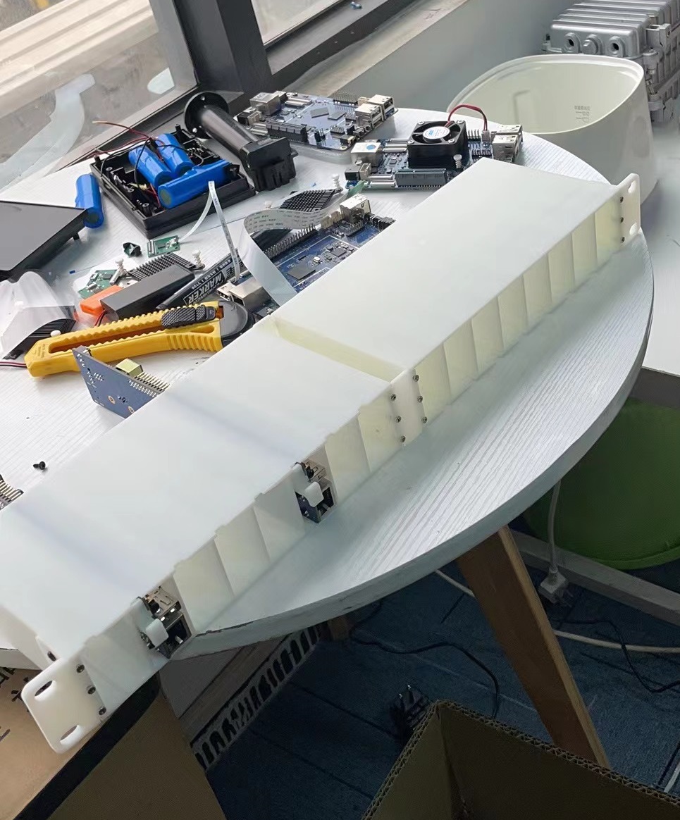
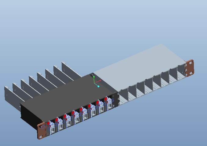
[[File:BLADE_1U_half_width_server_rack.jpg |400px|thumb|SOQuartz BLADE 3D Print 1U half width server rack]] | |||
[[File:BLADE_1U_full_width_server_rack.jpg |400px|thumb|SOQuartz BLADE 3D Print 1U full width server rack]] | |||
* SOQuartz Blade Baseboard Schematic and PCB Board Resource: | * SOQuartz Blade Baseboard Schematic and PCB Board Resource: | ||
** [https://files.pine64.org/doc/quartz64/SOQuartz-BLADE-Baseboard-Schematic-20220522.pdf SOQuartz BLADE 20220522 Schematic] | |||
** [https://files.pine64.org/doc/quartz64/SOQuartz-BLADE-PCB-Placement-20220522.pdf SOQuartz BLADE 20220522 PCB component Placement] | |||
** [https://files.pine64.org/doc/quartz64/BLADE%201U%20Rack_3D.stp SOQuartz BLADE 1U Rack STP file] | |||
[[File:BLADE_1U_rack_3D.jpg |400px]] | |||
SOQuartz module certifications: | |||
* [https://files.pine64.org/doc/cert/SOQuartz%20FCC%20Certificate-S21101902401001.pdf SOQuartz module FCC Certificate] | |||
* [https://files.pine64.org/doc/cert/SOQuartz%20CE%20Certificate-S21101902402001.pdf SOQuartz module CE EMC Certificate] | |||
== Datasheets for Components and Peripherals == | == Datasheets for Components and Peripherals == | ||
| Line 89: | Line 291: | ||
** [https://files.pine64.org/doc/datasheet/pine64/rtl8211e(g)-vb(vl)-cg_datasheet_1.6.pdf Realtek RTL8211 10/100/1000M Ethernet Transceiver] | ** [https://files.pine64.org/doc/datasheet/pine64/rtl8211e(g)-vb(vl)-cg_datasheet_1.6.pdf Realtek RTL8211 10/100/1000M Ethernet Transceiver] | ||
* WiFi/BT module info: | * WiFi/BT module info: | ||
** [https://files.pine64.org/doc/datasheet/rockpro64/AW-CM256SM_DS_DF_V1.9_STD.pdf Azurewave CM256SM 11AC WiFi + Bluetooth5.0 Datasheet]] | ** [https://files.pine64.org/doc/datasheet/rockpro64/AW-CM256SM_DS_DF_V1.9_STD.pdf Azurewave CM256SM 11AC WiFi + Bluetooth5.0 Datasheet] | ||
* i2C to PWM Controller user in BLADE info: | |||
** [https://files.pine64.org/doc/datasheet/quartz64/GP7101_cn_V1_qsxn.pdf GP7101 i2c to PWM Controller Datasheet in Chinese] | |||
** GP7101 i2c to PWM Controller Datasheet translated to English by neggles [[File:GP7101 cn V1 qsxn en.pdf]] | |||
** I<sup>2</sup>C address is 0x58 despite what datasheet says | |||
* PoE DC/DC Controller user in BLADE info: | |||
** [https://files.pine64.org/doc/datasheet/quartz64/SD4954B%20Datasheet.pdf Silan SD4954B PD and DC/DC Controller compatible with IEEE 802.3AF standard Datasheet] | |||
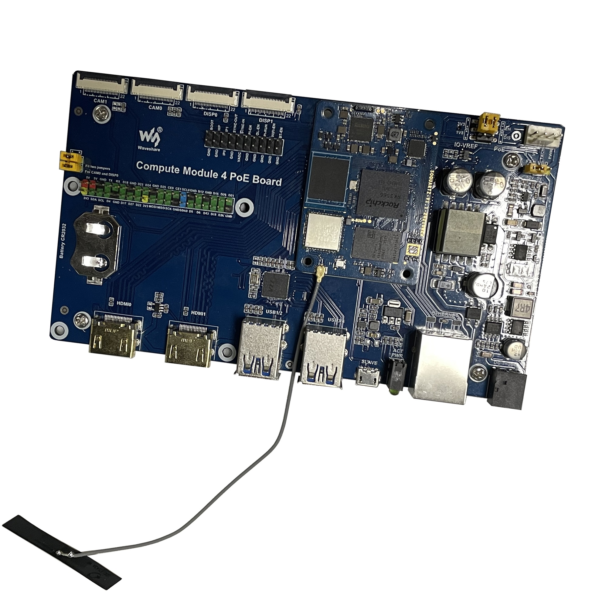
== SOQuartz Module with various CM4 carrier boards == | |||
* For CM4 carrier board comprehensive list, please visit [https://pipci.jeffgeerling.com/boards_cm Jeff Geerling collection] | |||
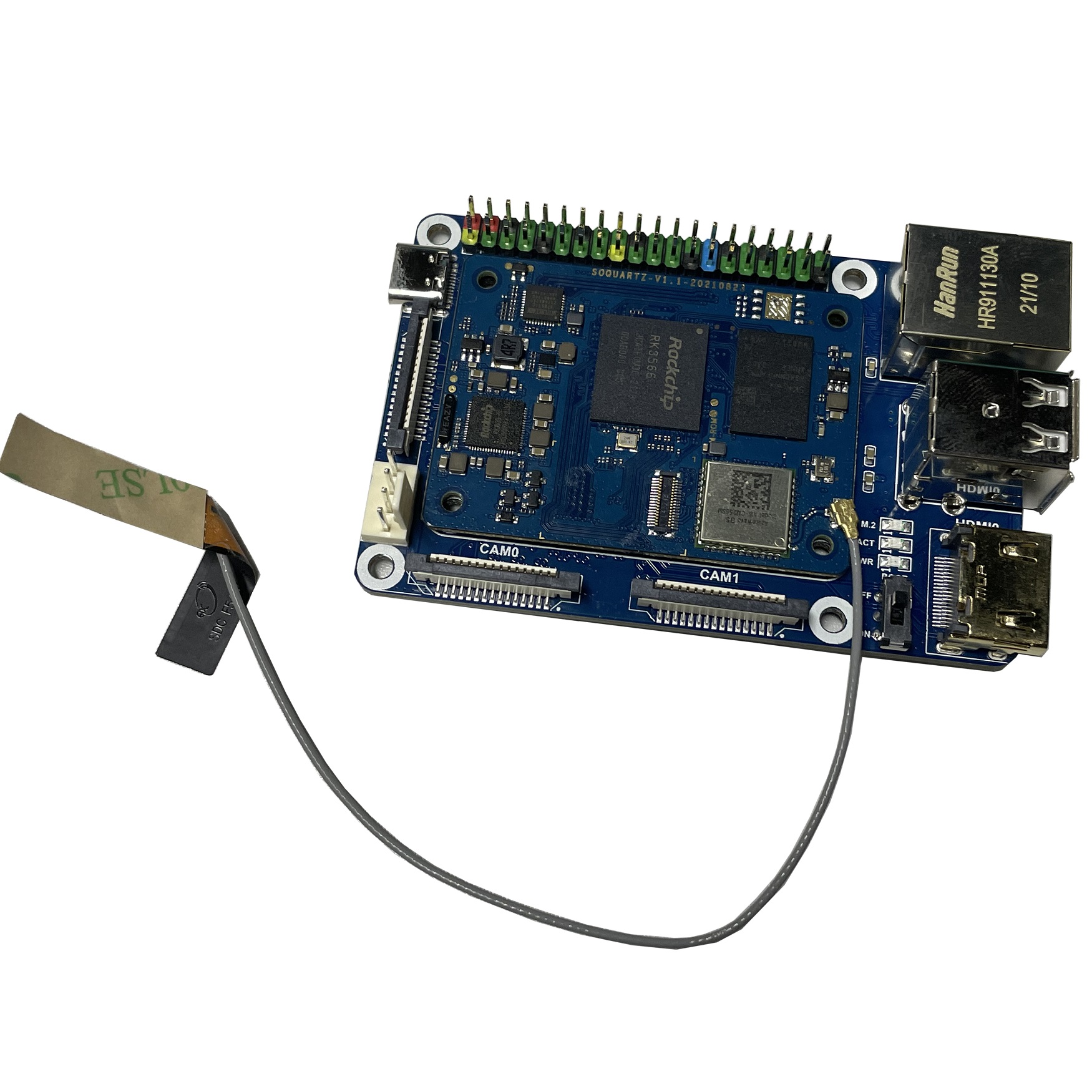
[[File:SOQuartz_with_DF_Robot_carrier_board.jpg|400px|thumb|SOQuartz with DF Robot CM4 Carrier Board]] | |||
[[File:SOQuartz_with_Waveshare_carrier_board.jpg|400px|thumb|SOQuartz with Waveshare CM4 Carrier Board]] | |||
[[File:SOQuartz_with_Waveshare_PoE_carrier_board.jpg|400px|thumb|SOQuartz with Waveshare CM4 PoE Board]] | |||
| Line 110: | Line 329: | ||
== | The '''Android 11 Stock''' images for SD boot for the SOQuartz module. This is test build. | ||
Download: | |||
* [https://files.pine64.org/os/Quartz64/android/SOQUARTZ_rk3566_android11_V1.0_sdboot_20211112.img.gz Direct download] from ''pine64.org'' (793MB, MD5 of the Gzip file ''be38ca999f9256bffd47d718f24003ab'', build 20211112) | |||
Notes: | |||
* Please unzip first and then using [https://files.pine64.org/os/Quartz64/android/SDDiskTool_v1.74.zip Rockchip SD card program tool ver 1.74] to program SD card | |||
* Please allow 3-5 minutes boot up time on first time for initialization | |||
The '''Android 11 Stock''' images for eMMC boot for the SOQuartz module. This is test build. | |||
Download: | |||
* [https://files.pine64.org/os/Quartz64/android/SOQUARTZ_rk3566_android11_V1.1_emmcboot_20211010.img.gz Direct download] from ''pine64.org'' (793MB, MD5 of the Gzip file ''3a29f0214898eed4d4e85e6ee8b9e4c7'', build 20211010) | |||
Notes: | |||
* Please unzip first and then using [https://files.pine64.org/os/Quartz64/android/RKDevTool_v3.13_for_window.zip Rockchip Android tool ver 3.13] to flash in | |||
* For Windows OS environment please install the [https://files.pine64.org/os/Quartz64/android/DriverAssitant_v5.1.1.zip DriverAssistant v5.11] driver first | |||
* The OTG port located on USB 3.0 port, needs USB type A to type A cable. | |||
* Please allow 3-5 minutes boot up time on first time for initialization | |||
== How-To == | |||
=== Building Mainline U-Boot === | |||
See [[Quartz64 Building U-Boot]]. | |||
== Troubleshooting == | |||
This section provides information on troubleshooting various common issues you may encounter using the SOQuartz. | |||
=== Thermal Issues === | |||
The SOQuartz SoM does not have a lot of copper to sink heat into. Therefore, it's recommended you use a heatsink such as the [https://www.waveshare.com/product/accessories/power-heat-sinks/heat-sinks/cm4-heatsink.htm Waveshare CM4 Heatsink], the [https://www.waveshare.com/product/accessories/power-heat-sinks/heat-sinks/cm4-heatsink-b.htm other Waveshare CM4 Heatsink], or the [https://pine64.com/product/small-fan-type-heatsink/ PINE64 Small Fan Type Heatsink]. Please be aware that the Waveshare heatsinks may interfere with any eMMC module, unless you use very thick (2-3 mm?) thermal pads. Local resellers may sell CM4 heatsinks or small stick-on heatsinks, so there's no need to order them from abroad unless it's cheaper. | |||
Alternatively, or in addition to this, a rectangle-shaped piece of 1 mm thick thermal pad can be sandwiched between the SoM and the carrier board. This allows the SoM to more efficiently sink heat into the larger mass of the base board. | |||
[[Category:SOQuartz]] [[Category:Quartz64]] | [[Category:SOQuartz]] | ||
[[Category:Quartz64]] | |||
Latest revision as of 19:32, 29 October 2024
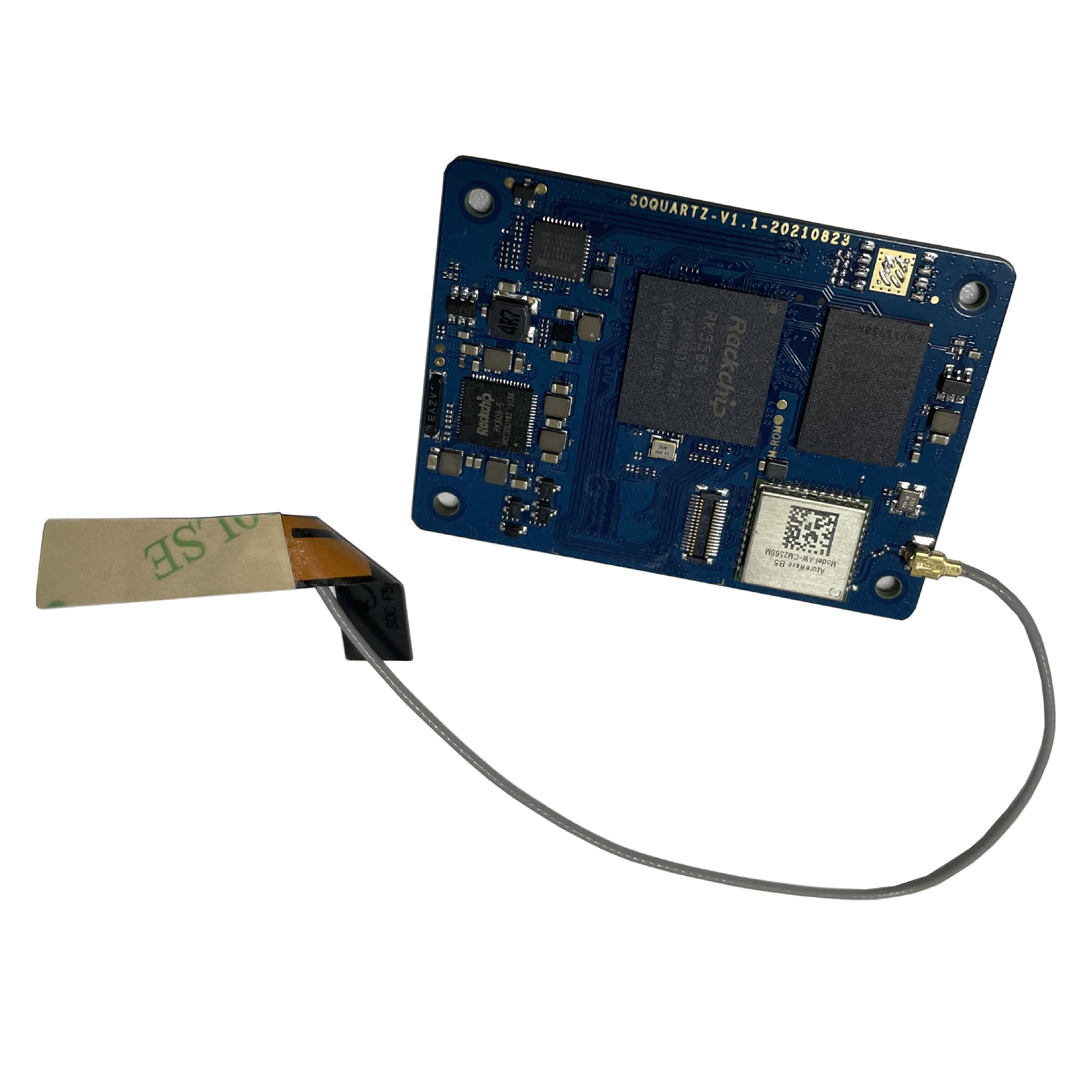
The SOQuartz is a RK3566 based compute module and parts of Quartz64 series.
Software releases
The SOQuartz software releases can be found in the article SOQuartz Software Releases.
SoC and Memory Specification
- Based on Rockchip RK3566
CPU Architecture
- Quad-core ARM Cortex-A55@1.8GHz
- AArch32 for full backwards compatibility with ARMv7
- ARM Neon Advanced SIMD (single instruction, multiple data) support for accelerated media and signal processing computation
- Includes VFP hardware to support single and double-precision operations
- ARMv8 Cryptography Extensions
- Integrated 32KB L1 instruction cache and 32KB L1 data cache per core
- 512KB unified system L3 cache
GPU (Graphics Processing Unit) Capabilities
- Mali-G52 2EE Bifrost GPU@800MHz
- 4x Multi-Sampling Anti-Aliasing (MSAA) with minimal performance drop
- 128KB L2 Cache configurations
- Supports OpenGL ES 1.1, 2.0, and 3.2
- Supports Vulkan 1.0 and 1.1
- Supports OpenCL 2.0 Full Profile
- Supports 1600 Mpix/s fill rate when at 800MHz clock frequency
- Supports 38.4 GLOP/s when at 800MHz clock frequency
Neural Process Unit NPU Capability
- Neural network acceleration engine with processing performance of up to 0.8 TOPS
- Supports integer 8 and integer 16 convolution operations
- Supports the following deep learning frameworks: TensorFlow, TF-lite, Pytorch, Caffe, ONNX, MXNet, Keras, Darknet
System Memory
- RAM Memory Variants: 2GB, 4GB, 8GB LPDDR4.
- Storage Memory: optional 128Mb SPI Flash and optional eMMC module from 8GB up to 128GB
Network
- 10/100/1000Mbps Ethernet
- WiFi 802.11 b/g/n/ac with Bluetooth 5.0
SOQuartz exposed peripherals
Displays / Cameras
- 1x HDMI
- 2x DSI
- 1x eDP (Instead of HDMI1)
- 1x LVDS (not available when dual-mode DSI)
- 1x CSI 4-line
Connectivity
- 1x Ethernet (1Gbit)
- 1x USB 2.0 OTG
- 1x SD Card (SD)
- 1x PCIe 1-Line
- 28x GPIO (TBD)
Connector Pins Definition
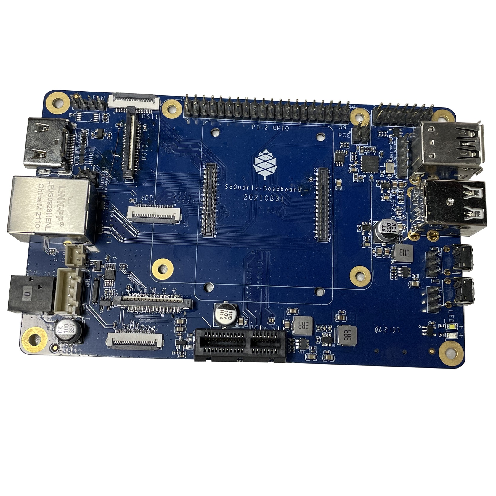
SOQuartz Model-A Baseboard Features
- Model "A" Baseboard Dimensions: 133mm x 80mm x 19mm
- Input Power: DC 12V @ 3A 5.5OD/2.1ID (IEC 60130-10 Type A) Barrel DC Jack connector
Storage
- microSD - bootable, support SDHC and SDXC, storage up to 2TB
- USB - 2 USB2.0 Host port
Expansion Ports
- MiPi-CSI - 1x 2 lanes, 1x 4 lanes
- MiPi-DSI - 1x 2 lanes, 1x 4 lanes
- 2x20 pins "Pi2" GPIO Header
- PCIe 1x open ended slot
- 1x5 pin USB Expansion Header (J15)
GPIO Pins
Attention! GPIOs are 3.3V!
Interesting alternate pin configurations are listed in [brackets].
| Assigned To | Pin no. | Pin no. | Assigned To |
|---|---|---|---|
| 3.3 V | 1 | 2 | 5 V |
| [I2C2_SDA_M1] GPIO4_B4_3V3 a | 3 | 4 | 5 V |
| [I2C2_SCL_M1] GPIO4_B5_3V3 a | 5 | 6 | GND |
| [GPCLK0] GPIO4_A4_3V3 | 7 | 8 | GPIO0_D1_3V3 [UART2_TX_M0] |
| GND | 9 | 10 | GPIO0_D0_3V3 [UART2_RX_M0] |
| [I2S1_MCLK_M1] GPIO3_C6_3V3 | 11 | 12 | GPIO3_C7_3V3 [I2S1_SCLK_M1] |
| GPIO4_A0_3V3 | 13 | 14 | GND |
| GPIO4_A2_3V3 | 15 | 16 | GPIO4_A3_3V3 |
| 3.3V | 17 | 18 | GPIO4_A1_3V3 |
| [SPI3_MOSI_M0] GPIO4_B2_3V3 | 19 | 20 | GND |
| [SPI3_MISO_M0] GPIO4_B0_3V3 | 21 | 22 | GPIO4_B1_3V3 |
| [SPI3_CLK_M0] GPIO4_B3_3V3 | 23 | 24 | GPIO4_A6_3V3 [SPI3_CS0_M0] |
| GND | 25 | 26 | GPIO4_A7_3V3 [SPI3_CS1_M0] |
| [I2C3_SDA_M0] GPIO1_A0_3V3 a | 27 | 28 | GPIO1_A1_3V3 [I2C3_SCL_M0] a |
| GPIO3_A5_3V3 | 29 | 30 | GND |
| GPIO3_D4_3V3 | 31 | 32 | GPIO3_D6_3V3 |
| GPIO3_D7_3V3 | 33 | 34 | GND |
| [I2S1_LRCK_M1] GPIO3_D0_3V3 | 35 | 36 | GPIO3_D5_3V3 |
| GPIO3_D3_3V3 | 37 | 38 | GPIO3_D2_3V3 [I2S1_SDI_M1] |
| GND | 39 | 40 | GPIO3_D1_3V3 [I2S1_SDO_M1] |
Notes
- pulled high to 3.3V through 2.2kOhm resistor
Source: Page 11 of the board schematics.
USB Expansion Header
| Pin no | Assigned To |
|---|---|
| 1 | USB2_HOST_5V |
| 2 | HOST_DM3 |
| 3 | HOST_DP3 |
| 4 | GND |
| 5 | GND |
Source: Page 10 of the board schematics.
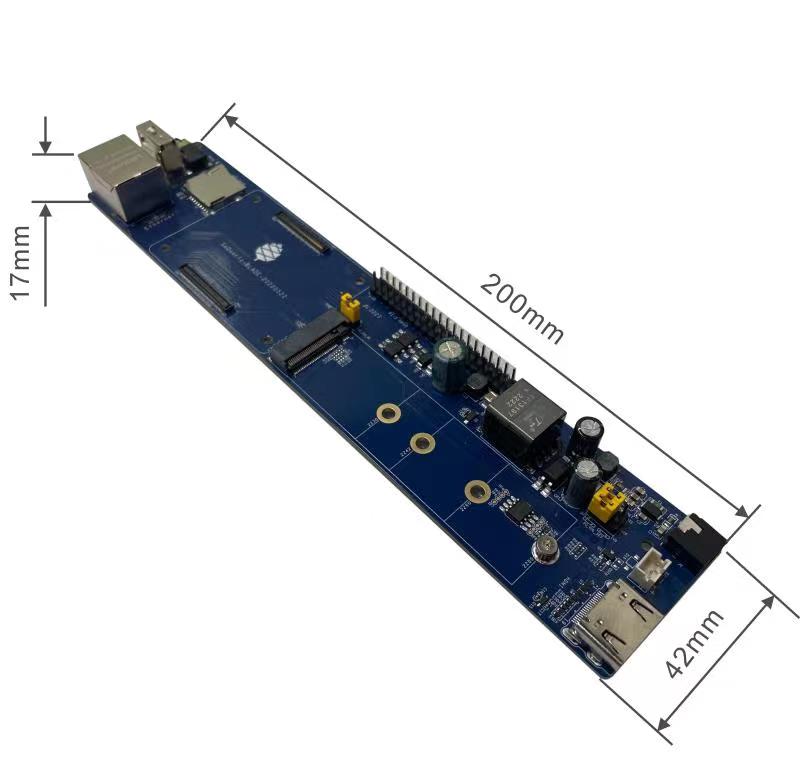
SOQuartz BLADE Baseboard Features
- SOQuartz BLADE Baseboard Dimensions: 200mm x 40mm x 15mm
- Input Power:
- DC 5V @ 3A 3.5OD/1.35ID (IEC 60130-10 Type H) Barrel DC Jack connector
- PoE
Storage
- microSD - bootable, support SDHC and SDXC, storage up to 2TB
- USB - USB2.0 Host port (with header for setting OTG ID pin)
Expansion Ports
- 2x20 pins "Pi2" GPIO Header
- HDMI video output
- M.2 slot
- PWM fan header
Jumpers
- OTG ID jumper
- GPIO voltage, select 3.3V or 1.8V
- PoE Enable
SOQuartz Module and Baseboard Information, Schematics, and Certifications
- SOQuartz Module Schematic:
- SOQuartz Model "A" Baseboard Schematic and PCB Board Resource:
- SOQuartz Model-A baseboard 20220522 Schematic PDF file
- SOQuartz Model-A baseboard 20220522 Schematic DSN source file
- SOQuartz SOQuartz Model-A baseboard 20220522 PCB Top Component Placement
- SOQuartz SOQuartz Model-A baseboard 20220522 PCB Bottom Component Placement
- SOQuartz Model-A baseboard 20220522 PCB DSN file
- SOQuartz Model-A baseboard 20220522 PCB Gerber file
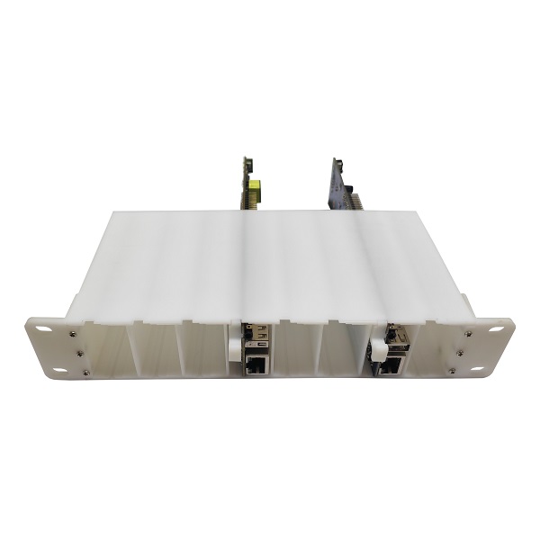
- SOQuartz Blade Baseboard Schematic and PCB Board Resource:
SOQuartz module certifications:
Datasheets for Components and Peripherals
- Rockchip RK3566 SoC information:
- Rockchip PMU (Power Management Unit) Information:
- DDR4 information:
- eMMC information:
- SPI NOR Flash information:
- Ethernet PHY information:
- WiFi/BT module info:
- i2C to PWM Controller user in BLADE info:
- GP7101 i2c to PWM Controller Datasheet in Chinese
- GP7101 i2c to PWM Controller Datasheet translated to English by neggles File:GP7101 cn V1 qsxn en.pdf
- I2C address is 0x58 despite what datasheet says
- PoE DC/DC Controller user in BLADE info:
SOQuartz Module with various CM4 carrier boards
- For CM4 carrier board comprehensive list, please visit Jeff Geerling collection
BSP Linux SDK
BSP Linux SDK ver 4.19 for Quartz64 model A SBC
- Direct Download from pine64.org
- MD5 (TAR-GZip file): 24554419aec29700add97167a3a4c9ed
- File Size: 32.67.00GB
Android SDK
Android 11 SDK for Quartz64 model A SBC
- Direct Download from pine64.org
- MD5 (TAR-GZip file): 77c2ff57ea3372fb04da7fb49e17d12b
- File Size: 79.00GB
- Just the boot blobs (<1MB): File:Rk35-blobs.tar.gz
The Android 11 Stock images for SD boot for the SOQuartz module. This is test build.
Download:
- Direct download from pine64.org (793MB, MD5 of the Gzip file be38ca999f9256bffd47d718f24003ab, build 20211112)
Notes:
- Please unzip first and then using Rockchip SD card program tool ver 1.74 to program SD card
- Please allow 3-5 minutes boot up time on first time for initialization
The Android 11 Stock images for eMMC boot for the SOQuartz module. This is test build.
Download:
- Direct download from pine64.org (793MB, MD5 of the Gzip file 3a29f0214898eed4d4e85e6ee8b9e4c7, build 20211010)
Notes:
- Please unzip first and then using Rockchip Android tool ver 3.13 to flash in
- For Windows OS environment please install the DriverAssistant v5.11 driver first
- The OTG port located on USB 3.0 port, needs USB type A to type A cable.
- Please allow 3-5 minutes boot up time on first time for initialization
How-To
Building Mainline U-Boot
Troubleshooting
This section provides information on troubleshooting various common issues you may encounter using the SOQuartz.
Thermal Issues
The SOQuartz SoM does not have a lot of copper to sink heat into. Therefore, it's recommended you use a heatsink such as the Waveshare CM4 Heatsink, the other Waveshare CM4 Heatsink, or the PINE64 Small Fan Type Heatsink. Please be aware that the Waveshare heatsinks may interfere with any eMMC module, unless you use very thick (2-3 mm?) thermal pads. Local resellers may sell CM4 heatsinks or small stick-on heatsinks, so there's no need to order them from abroad unless it's cheaper.
Alternatively, or in addition to this, a rectangle-shaped piece of 1 mm thick thermal pad can be sandwiched between the SoM and the carrier board. This allows the SoM to more efficiently sink heat into the larger mass of the base board.
