|
|
| (22 intermediate revisions by 2 users not shown) |
| Line 1: |
Line 1: |
| [[File:PineVoice-2.jpg|thumb|right|The Ox64]] | | [[File:PineVoice-2.jpg|thumb|right|The PineVoice]] |
| [[File:RISC-V.png|thumb|right|Powered by RISC-V]]
| |
|
| |
|
| The '''PineVoice''' is a RISC-V based smart speaker based on the Bouffalo Lab BL606P RISC-V SoC with C906 64-bit and E907 32-bit CPU cores supported by 16 MB of embedded PSRAM memory, and with built-in WiFi, Bluetooh and Zigbee radio interfaces. | | The '''PineVoice''' is a compact RISC-V based smart speaker based on the Bouffalo Lab BL606P RISC-V SoC. It is designed as a local voice assistant satellite, with Wi-Fi, Bluetooth, a speaker, a dual microphone array, buttons, and a center ring LED. |
|
| |
|
| == Software Releases ==
| | The factory firmware is open-source and provides Wi-Fi provisioning over Improv, local wake word detection, and voice assistant connectivity through the Wyoming protocol, making PineVoice compatible with assistance platforms such as Home Assistant. |
|
| |
|
| === Quick Links to the Source of OS Images Build === | | == Specifications == |
|
| |
|
| There is a community effort to bring updated kernels, peripherals and buildroot - Lots of communication happening in the #ox64-nutcracker channel.
| | === SoC and memory === |
|
| |
|
| * [https://github.com/openbouffalo/buildroot_bouffalo buildroot] bringing all the work below together with a bootable kernel and updated filesystem images for SD cards
| | [[File:RISC-V.png|thumb|right|Powered by RISC-V]] |
| * [https://github.com/openbouffalo/OBLFR OpenBouffalo Firmware] low_load drivers by Fishwaldo and others
| | [[File:BL606P_Block_Diagram.png|500px|thumb|right|BL606P block diagram]] |
|
| |
|
| | PineVoice is based on the [https://bouffalolab.com/product/?type=detail&id=16 Bouffalo Lab BL606P]. |
|
| |
|
| | | ==== CPU architecture ==== |
| Toolchain:
| |
| | |
| * elf_newlib_toolchain/bin/riscv64-unknown-elf-gcc (Xuantie-900 elf newlib gcc Toolchain V2.2.5 B-20220323) 10.2.0
| |
| * linux_toolchain/bin/riscv64-unknown-linux-gnu-gcc (Xuantie-900 linux-5.10.4 glibc gcc Toolchain V2.2.4 B-20211227) 10.2.0
| |
| * cmake version 3.19.3
| |
| | |
| === Software Development Kits === | |
| * [https://github.com/bouffalolab/bl_mcu_sdk BL808 MCU SDK]
| |
| * [https://dev.bouffalolab.com/download BLDevCube Flashing Tool for Windows, macOS and Ubuntu x64]
| |
| * [https://wiki.pine64.org/wiki/File:Ox64_BL808UART_connect.pdf Ox64 UART Flashing Guide], see the [https://gist.github.com/lupyuen/7a0c697b89abccda8e38b33dfe5ebaff notes]
| |
| | |
| | |
| == SoC and Memory Specification ==
| |
| | |
| [[File:Bouffalo_Lab_icon.png|right]]
| |
| | |
| Based on the [https://en.bouffalolab.com/product/ Bouffalo Lab BL606P]
| |
| | |
| [[File:BL606P_Block_Diagram.png|500px]]
| |
| | |
| === CPU Architecture ===
| |
| | |
| [[File:T-Head.png|right|200px]]
| |
|
| |
|
| T-Head C906 480 MHz 64-bit RISC-V CPU: | | T-Head C906 480 MHz 64-bit RISC-V CPU: |
| Line 43: |
Line 20: |
| * Supports RISC-V RV64IMAFCV instruction architecture | | * Supports RISC-V RV64IMAFCV instruction architecture |
| * Five-stage single-issue sequentially executed pipeline | | * Five-stage single-issue sequentially executed pipeline |
| * Level-1 instruction and data cache of Harvard architecture, with a size of 32 KB and a cache line of 64B | | * Level-1 instruction and data cache of Harvard architecture, with a size of 32 KiB and a cache line of 64 bytes |
| * Sv39 memory management unit, realizing the conversion of virtual and real addresses and memory management | | * Sv39 memory management unit |
| * jTLB that supports 128 entries
| |
| * Supports AXI 4.0 128-bit master interface | | * Supports AXI 4.0 128-bit master interface |
| * Supports core local interrupt (CLINT) and platform-level interrupt controller (PLIC) | | * Supports core local interrupt (CLINT) and platform-level interrupt controller (PLIC) |
| * With 80 external interrupt sources, 3 bits for configuring interrupt priority
| | * Compatible with RISC-V PMP |
| * Supports BHT (8K) and BTB
| |
| * Compatible with RISC-V PMP, 8 configurable areas | |
| * Supports hardware performance monitor (HPM) units
| |
| * See [https://www.t-head.cn/product/c906?lang=en here]
| |
|
| |
|
| T-Head E907 320 MHz 32-bit RISC-V CPU: | | T-Head E907 320 MHz 32-bit RISC-V CPU: |
|
| |
|
| * Supports RISC-V RV32IMAFCP instruction set | | * Supports RISC-V RV32IMAFCP instruction set |
| * Supports RISC-V 32-bit/16-bit mixed instruction set | | * Supports RISC-V 32-bit and 16-bit mixed instruction set |
| * Supports RISC-V machine mode and user mode | | * Supports RISC-V machine mode and user mode |
| * Thirty-two 32-bit integer general purpose registers (GPR) and thirty-two 32-bit/64-bit floating-point GPRs | | * Integer and floating-point pipelines |
| * Integer (5-stage)/floating-point (7-stage), single-issue, sequentially executed pipeline
| |
| * Supports AXI 4.0 main device interface and AHB 5.0 peripheral interface | | * Supports AXI 4.0 main device interface and AHB 5.0 peripheral interface |
| * 32K instruction cache, two-way set associative structure | | * 32 KiB instruction cache |
| * 16K data cache, two-way set associative structure | | * 16 KiB data cache |
| * See [https://www.t-head.cn/product/e907?lang=en here]
| |
| | |
|
| |
|
| | T-Head E902 150 MHz 32-bit RISC-V CPU. |
|
| |
|
| === System Memory === | | ==== Memory and storage ==== |
| * Embedded 16MB PSRAM
| |
|
| |
|
| == Smart Speaker Module Features ==
| | * 32 MiB pSRAM |
| | * 788 KiB SRAM |
| | * 16 MiB flash storage |
|
| |
|
| === Network === | | === Hardware features === |
| * 2.4 GHz 1T1R WiFi 802.11 b/g/n
| |
| * Bluetooth 5.x Dual-mode (BT+BLE)
| |
| * Zigbee
| |
|
| |
|
| | ==== Wireless ==== |
|
| |
|
| === Storage ===
| | * Wi-Fi 802.11 b/g/n |
| * On-board 128 Mbit (16 MB) XSPI NOR flash memory | | * Bluetooth 5.2 Dual-mode (BT+BLE) |
|
| |
|
| === Expansion Ports === | | ==== Audio ==== |
| * USB 2.0 OTG port
| |
|
| |
|
| | * Built-in speaker tuned for voice applications |
| | * Dual microphone array |
|
| |
|
| === Audio === | | ==== Controls and indicators ==== |
| * Microphone
| |
| * Speaker
| |
|
| |
|
| == Board Information, Schematics and Certifications ==
| | [[File:Pinevoice-top-view-labels.png|600px|thumb|PineVoice buttons view]] |
|
| |
|
| | * Button controls |
| | * Center LED ring and button |
| | * Hardware mute button |
|
| |
|
| * Module dimensions: 65 mm x 65 mm x 19 mm x 66 mm
| | ==== Power and connectivity ==== |
| * Input power: 5 V, 2 A USB-C ports
| |
|
| |
|
| Production version schematic:
| | * USB-C power input and data channel |
| | * Debug UART exposed on unused USB-C pins |
|
| |
|
| * [https://files.pine64.org/doc/PineVoice/PineVoice%20Bottom%20Board%20Schematics-20250921.pdf PineVoice Bottom Board Schematic 20250921]
| | ==== Package contents ==== |
|
| |
|
| | * USB-A to USB-C power cable |
|
| |
|
| Certifications:
| | == Software == |
| * Disclaimer: Please note that PINE64 SBC is not a "final" product and in general certification is not necessary.
| |
| * Not yet available
| |
|
| |
|
| == Datasheets for Components and Peripherals ==
| | The factory PineVoice firmware turns PineVoice into a voice assistant satellite. Firmware uses Alibaba's AliOS, specifically the YoC/YoCop variation. |
|
| |
|
| Bouffalo BL808 SoC information:
| | === Supported features === |
| * [https://files.pine64.org/doc/datasheet/pinevoice/BL606P_DS_en_1.2.pdf Bouffalo Lab BL606P SoC Datasheet]
| |
| * [https://files.pine64.org/doc/datasheet/pinevoice/BL606P_Product_Brief_v1.0.pdf Bouffalo Lab BL606P SoC Reference Manual]
| |
|
| |
|
| SPI NOR Flash information:
| | The current factory firmware supports: |
| * [https://files.pine64.org/doc/datasheet/ox64/gd25lq16e_rev1.2_20210108.pdf GigaDevice 16Mb XSPI-Flash Datasheet]
| |
| * [https://files.pine64.org/doc/datasheet/star64/gd25lq128e_rev1.0_20210513.pdf GigaDevice 128Mb XSPI-Flash Datasheet]
| |
| * [https://wiki.pine64.org/images/5/5d/W25Q128JW_RevB_11042019-1761358.pdf Winbond 128Mb QSPI-Flash Datasheet] (W25Q128JWSQ)
| |
|
| |
|
| == Compatible UARTs when in bootloader mode ==
| | * Wi-Fi provisioning using the [https://www.improv-wifi.com/ Improv] protocol over Bluetooth Low Energy |
| | * Wyoming satellite for compatible assistance applications |
| | * Wyoming mDNS auto-discovery for compatible assistance applications |
| | * Local wake word detection using [https://github.com/OHF-Voice/micro-wake-word MicroWakeWord] |
|
| |
|
| When the Ox64 is in bootloader mode, some UARTs are unable to communicate with it. When this is the case, utilities such as BLDevCube are unable to actually program the device. If you see "Shake hand fail" and an empty ack, and your device is in bootloader mode, then it is likely an incompatible UART.
| | === Source code === |
|
| |
|
| The below devices have been tested and verified as working: | | The PineVoice SmartSpeaker SDK source code is available on [https://codeberg.org/pine64/pinevoice_smartspeaker_sdk Codeberg] and [https://github.com/pine64/pinevoice_smartspeaker_sdk GitHub]. |
| * Raspberry Pi Pico - running the following [https://github.com/sanjay900/ox64-uart/releases/tag/v1.1 UART firmware] (GP4 and GP5 are used for port 0, GP12 and GP13 for port 1)
| |
| * Compiled binary for Pi Pico and connectivity diagram is [https://github.com/Kris-Sekula/Pine64_Ox64_SBC/tree/main/uart here]
| |
| * ESP32 with CP210x - bridge the EN pin to ground to disable the ESP32 itself, and then connect the TX on the esp32 to 14 on the Ox64 and RX to pin 15. Note that only baud rate 115200 works, and this doesn't seem to work for everyone)
| |
| * Stand-alone CP2102 dongle works at 115200 baud. Brand used was HiLetgo.
| |
| * STM32F401 BlackPill - running the [https://github.com/blackmagic-debug/blackmagic/tree/main/src/platforms/blackpillv2 Black Magic Debug] firmware
| |
| * STM32F103C8T6 BluePill - running Black Magic Debug.
| |
| * Some UART adapters based on the FT232H (note that the FT232RL does not work, and neither does the Pine 64 JTAG)
| |
| * Some CH340G based adapters work and some don't.
| |
| * Flipper Zero UART-Bridge works with baud rate set to 230400.
| |
|
| |
|
| == Resources and Articles == | | == Wi-Fi setup == |
|
| |
|
| == Development Efforts ==
| | PineVoice implements the open-source [https://www.improv-wifi.com/ Improv] Wi-Fi provisioning protocol. Any application supporting this protocol can set up Wi-Fi on PineVoice. |
| * [https://twitter.com/gamelaster/status/1583916501400068096 Ox64 boots Linux successfully]
| |
|
| |
|
| | === Entering provisioning mode === |
|
| |
|
| == Building ==
| | On first boot, PineVoice automatically enters Wi-Fi provisioning mode. While in this mode, the ring LED blinks yellow. |
| Start the building process cloning both the upstream Buildroot repository and the Buildroot Bouffalo overlay repository:
| |
|
| |
|
| $ mkdir -p ~/ox64
| | If the ring LED is not blinking yellow, the speaker is not in provisioning mode. Hold the dot button for 15 seconds to reset Wi-Fi setup and return PineVoice to provisioning mode. After releasing the button, PineVoice should restart and launch provisioning mode. |
| $ cd ~/ox64
| |
| $ git clone https://github.com/buildroot/buildroot
| |
| $ git clone https://github.com/openbouffalo/buildroot_bouffalo
| |
|
| |
|
| Define an environment variable for the Buildroot Bouffalo overlay path:
| | === Provisioning through the web === |
|
| |
|
| $ export BR_BOUFFALO_OVERLAY_PATH=$(pwd)/buildroot_bouffalo
| | Web provisioning requires a browser with Web Bluetooth API support. See the [https://caniuse.com/web-bluetooth Web Bluetooth support table] for browser compatibility. |
|
| |
|
| Change directory into the cloned Buildroot folder:
| | Open the PineVoice documentation website on a PC or phone with Bluetooth 4.0 Low Energy support and use the Improv provisioning button there. If that button does not work, try provisioning from the [https://www.improv-wifi.com/ Improv website]. |
|
| |
|
| $ cd ~/ox64/buildroot
| | === Provisioning through Home Assistant === |
|
| |
|
| Apply the default configuration for Pine64 Ox64:
| | Home Assistant supports [https://www.home-assistant.io/integrations/improv_ble/ Improv via BLE]. This feature must be configured in Home Assistant and requires working Bluetooth support. See the [https://www.home-assistant.io/integrations/bluetooth Home Assistant Bluetooth documentation] for details. |
|
| |
|
| $ make BR2_EXTERNAL=$BR_BOUFFALO_OVERLAY_PATH pine64_ox64_defconfig
| | [[File:Improv-card.png|400px|thumb|Improv card in Home Assistant]] |
|
| |
|
| Use the `menuconfig` tool to adjust the build settings:
| | After successful Wi-Fi provisioning, continue with assistance setup. |
|
| |
|
| $ make menuconfig
| | == Assistance setup == |
|
| |
|
| Within `menuconfig`, configure the following:
| | PineVoice implements the open-source [https://github.com/OHF-Voice/wyoming Wyoming] protocol for voice assistants. Any assistance application supporting this protocol can communicate with PineVoice. |
|
| |
|
| * Select `Target Options`
| | After PineVoice has joined the Wi-Fi network, the center ring LED should slowly breathe in a dim magenta color. This means PineVoice is connected to Wi-Fi and is waiting for an assistance application to connect through the Wyoming protocol. |
| * Enable `Integer Multiplication and Division (M)`
| |
| * Enable `Atomic Instructions (A)` using space key
| |
| * Enable `Single-precision Floating-point (F)`
| |
| * Enable `Double-precision Floating-point (D)`
| |
| * Select `Target ABI`, set it to `lp64d` and `press Exit`
| |
| * Select `Toolchain`, enable `Fortran support`, enable `OpenMP support`, and Save & Exit
| |
|
| |
|
| Initiate the build process, but first make sure that your `PATH` variable contains no spaces. For Arch Linux distrubution you may also need to install extra-packages with `sudo pacman -S cpio rsync bc`.
| | === Adding PineVoice to Home Assistant === |
|
| |
|
| $ make
| | Home Assistant supports Wyoming Protocol devices through the [https://www.home-assistant.io/integrations/wyoming/ Wyoming Protocol integration]. Home Assistant must also have a working Assist voice pipeline. Follow the [https://www.home-assistant.io/voice_control/ Home Assistant Assist documentation] if Assist has not been configured yet. |
|
| |
|
| Buildroot will output the needed files to the `~/ox64/buildroot/output/images` directory in about 1 hour, according to your computer processing resources and internet connection speed.
| | ==== Automatic setup ==== |
|
| |
|
| == Flashing ==
| | PineVoice supports mDNS auto-discovery. If Home Assistant can see mDNS announcements on the same network, PineVoice should appear automatically as a discovered Wyoming Protocol device. |
| This page explains how to flash an Ox64 board and a microSD card to boot the system. You will need a Linux computer, a serial UART adapter, the Ox64 board, and a microSD card.
| |
|
| |
|
| === Prepare images for flashing ===
| | # Open Home Assistant. |
| | # Go to '''Settings''' -> '''Devices & services'''. |
| | # Look for a discovered '''Wyoming Protocol''' device. |
| | # Select '''Configure'''. |
| | # Follow the on-screen instructions to finish adding PineVoice. |
|
| |
|
| Download the Ox64 images from the latest OpenBouffalo release. You may skip this step if you built your own images as per the instructions in the link:/documentation/Ox64/Software/Building/[Building] page.
| | After setup completes, PineVoice should be available as an Assist satellite in Home Assistant. |
|
| |
|
| $ mkdir -p ~/ox64/openbouffalo
| | ==== Manual setup ==== |
| $ cd ~/ox64/openbouffalo
| |
| $ wget https://github.com/openbouffalo/buildroot_bouffalo/releases/download/v1.0.1/bl808-linux-pine64_ox64_full_defconfig.tar.gz
| |
| $ tar -xvzf bl808-linux-pine64_ox64_full_defconfig.tar.gz
| |
| $ cd ~/ox64/openbouffalo/firmware
| |
| $ xz -v -d -k sdcard-pine64_ox64_full_defconfig.img.xz
| |
| $ mv sdcard-pine64_ox64_full_defconfig.img sdcard.img
| |
|
| |
|
| ==== Optional: create a combined SoC image ====
| | If PineVoice does not appear automatically, add it manually through the Wyoming Protocol integration. |
|
| |
|
| Use the following commands to combine _m0_lowload_bl808_m0.bin_, _d0_lowload_bl808_d0.bin_, and _bl808-firmware.bin_ into a single image. This is mainly useful for troubleshooting (e. g. when using DevCube v1.8.4 or later).
| | # Find the IP address of PineVoice in the client list of your Wi-Fi router or access point. |
| | # Open Home Assistant. |
| | # Go to '''Settings''' -> '''Devices & services'''. |
| | # Select '''Add integration'''. |
| | # Search for and select '''Wyoming Protocol'''. |
| | # Enter the PineVoice IP address as the host. |
| | # Enter <code>10700</code> as the port. |
| | # Follow the on-screen instructions to finish adding PineVoice. |
|
| |
|
| $ cd ~/ox64/openbouffalo/firmware # if you downloaded pre-built images
| | ==== Troubleshooting ==== |
| # or
| |
| $ cd ~/ox64/buildroot/output/images # if you built your own images
| |
|
| |
|
| $ fallocate -l 0x800000 bl808-combined.bin
| | Known issues currently being investigated: |
| $ dd conv=notrunc if=m0_lowload_bl808_m0.bin of=bl808-combined.bin
| |
| $ dd conv=notrunc if=d0_lowload_bl808_d0.bin of=bl808-combined.bin seek=$((0x100000))B
| |
| $ cat bl808-firmware.bin >> bl808-combined.bin
| |
|
| |
|
| ==== Check that you have the required files for flashing ====
| | * If PineVoice is stuck in the listening state or Home Assistant does not react when Assist starts, restart PineVoice. |
| | * If adding the device fails, press Retry / Try Again, or try to add PineVoice again. |
|
| |
|
| $ cd ~/ox64/openbouffalo/firmware # if you downloaded pre-built images
| | If Home Assistant cannot connect to PineVoice, check the following: |
| # or
| |
| $ cd ~/ox64/buildroot/output/images # if you built your own images
| |
|
| |
|
| $ ls -1 *808*.bin *.img
| | * PineVoice and Home Assistant are on the same network or VLAN. |
| | * The center ring LED is breathing in dim magenta. |
| | * The IP address entered in Home Assistant is the current IP address of PineVoice. |
| | * TCP port <code>10700</code> is reachable from the Home Assistant system. |
| | * mDNS is allowed on the network if using automatic discovery. |
|
| |
|
| Expected files:
| | For more information, see the Home Assistant [https://www.home-assistant.io/integrations/wyoming/ Wyoming Protocol integration] documentation. |
|
| |
|
| * `bl808-combined.bin` -- If you created the combined image.
| | === Testing === |
| * `bl808-firmware.bin` -- OpenSBI and UBoot DTB files. Runs on the D0 core.
| |
| * `d0_lowload_bl808_d0.bin` -- Startup code for the D0 core.
| |
| * `m0_lowload_bl808_m0.bin` -- Startup code for the M0 core.
| |
| * `sdcard.img` -- Kernel and root filesystem. Runs on the D0 core.
| |
|
| |
|
| === Set up your UART adapter ===
| | After PineVoice is added to an assistance application, Assist can be triggered in the following ways: |
|
| |
|
| In this section we will configure and wire up a UART adapter in order to flash the Ox64. Choose one of the options below based on the hardware available to you; the first two are the most convenient since they minimise the number of times you will need to swap electrical connections.
| | * Say the wake word: "Hey Jarvis" |
| | * Press the center button in the LED ring |
|
| |
|
| ==== Option 1: Raspberry Pi Pico ====
| | After triggering Assist, say a command supported by the assistance application. The assistance application should reply accordingly. |
|
| |
|
| First, download the Raspberry Pi Pico firmware that allows it to act as a serial UART adapter:
| | == LED ring lightshows and controls == |
|
| |
|
| $ mkdir -p ~/ox64/pico
| | The center LED ring shows the current state of PineVoice. For most actions and states, light shows are used instead of voice feedback so PineVoice does not unexpectedly disturb the user, for example during the night. Active-state light shows, such as the dim cyan standby light, are intentionally kept dim so they remain visible without being distracting in a dark room. |
| $ cd ~/ox64/pico
| |
| $ wget https://github.com/Kris-Sekula/Pine64_Ox64_SBC/raw/main/uart/picoprobe.uf2
| |
|
| |
|
| Put the Raspberry Pi Pico board into programming mode:
| | === Startup and setup === |
|
| |
|
| * Press the BootSel button
| | {| class="wikitable" |
| * Apply power by plugging the USB cable to PC
| | ! Light show |
| * Release the BootSel button
| | ! Meaning |
| | |- |
| | | Dim white fade-in/fade-out, once |
| | | Boot-up lightshow. PineVoice has started. |
| | |- |
| | | Yellow breath, loop |
| | | PineVoice is in provisioning mode and is ready to connect to Wi-Fi through the Improv protocol. |
| | |- |
| | | Green fade-in/fade-out, once |
| | | Identification signal during provisioning, used to identify the paired PineVoice. |
| | |- |
| | | Dim orange breath, loop |
| | | PineVoice is trying to connect to Wi-Fi. |
| | |- |
| | | Dim magenta breath, loop |
| | | PineVoice is waiting for a Wyoming client to connect. |
| | |} |
|
| |
|
| NOTE: As an alternative to pressing the BootSel button, you can also connect the probe point `TP6` (located on the bottom of the Pico board) to any ground point (e. g. pin 28).
| | === Assistant states === |
|
| |
|
| The Pico will now appear as a USB mass storage device. Copy the `UF2` file to program it:
| | {| class="wikitable" |
| | ! Light show |
| | ! Meaning |
| | |- |
| | | Dim cyan, still |
| | | PineVoice is active and in standby, waiting for the user to press the center button or say the wake word. |
| | |- |
| | | Blue-cyan-blue breath, loop |
| | | PineVoice is listening to the user's voice input. |
| | |- |
| | | Dim purple, still |
| | | PineVoice is processing the user's input. |
| | |- |
| | | Slow green breath, loop |
| | | PineVoice is answering. |
| | |} |
|
| |
|
| $ cp ~/ox64/pico/picoprobe.uf2 /media/<user>/RPI-RP2
| | === Action feedback === |
|
| |
|
| Next, connect the Ox64 board to the Pico according to the following wiring diagram:
| | {| class="wikitable" |
| | ! Light show |
| | ! Meaning |
| | |- |
| | | White fade-in, once |
| | | Volume up. |
| | |- |
| | | White fade-out, once |
| | | Volume down. |
| | |- |
| | | Red fade-out, once |
| | | An error happened or the action failed. |
| | |} |
|
| |
|
| [cols="1,1,1"]
| | === Button controls === |
| |===
| |
| | Ox64 | PI PICO | /dev/tty
| |
|
| |
|
| | uart0_Tx_GPIO14_pin1 | | [[File:Pinevoice-top-view.png|400px|thumb|PineVoice buttons view]] |
| | uart0_Rx_pin17 | |
| | ACM1 for flashing | |
|
| |
|
| | uart0_Rx_GPIO15_pin2
| | PineVoice has five top buttons for voice control, volume, microphone mute, and provisioning. |
| | uart0_Tx_pin16
| |
| | ACM1 for flashing
| |
|
| |
|
| | Rxd_GPIO17_pin31
| | * '''Center LED ring button''' - starts a voice command session. |
| | uart1_Tx_pin6
| | * '''+ button''' - increases the volume. |
| | ACM0 for serial console
| | * '''- button''' - decreases the volume. |
| | * '''Microphone button''' - hardware microphone mute. The button shines red while microphone mute is active. |
| | * '''Dot / user button''' - currently used to enter provisioning mode. Hold it for 15 seconds to reset Wi-Fi setup and return PineVoice to provisioning mode. |
|
| |
|
| | Txd_GPIO16_pin32
| | == Voice feedback and wake word detection == |
| | uart1_Rx_pin7
| |
| | ACM0 for serial console
| |
|
| |
|
| | gnd_pin38
| | PineVoice mostly uses light shows instead of voice feedback. Voice feedback is generally reserved for direct user interaction. |
| | gnd_pin38/3
| |
| |
| |
|
| |
|
| | vbus5v_pin40
| | Audio feedback is currently used in the following cases: |
| | vbus5v_pin40
| |
| |
| |
| |===
| |
|
| |
|
| With the Pico flashed and wired as per the instructions above, we have access to two of the Ox64's UART ports at the same time. This configuration eliminates the need to switch the physical connections for flashing or testing the system.
| | * '''Wi-Fi provisioning started''' - played when Wi-Fi provisioning starts, including on first boot. |
| | * '''Wi-Fi provisioning succeeded or failed''' - played when Wi-Fi provisioning finishes successfully or fails. |
| | * '''Wyoming satellite is disconnected''' - played when Assist is attempted, but the Wyoming satellite/client is not connected. |
| | * '''Wi-Fi is disconnected''' - played when Assist is attempted, but PineVoice is not connected to Wi-Fi. |
|
| |
|
| Reconnect the Pico to your computer's USB port and verify that we have access to all the serial ports we need:
| | PineVoice uses [https://github.com/OHF-Voice/micro-wake-word MicroWakeWord] for local wake word detection. |
|
| |
|
| $ ls /dev/ttyACM*
| | For now, PineVoice uses the "Hey Jarvis" model from the [https://github.com/esphome/micro-wake-word-models ESPHome MicroWakeWord models] project. Wake word recognition may vary depending on the speaker's voice, pronunciation, distance from the device, and background noise. |
|
| |
|
| Expected result:
| | Future firmware updates are expected to add support for custom MicroWakeWord-compatible models. There are also plans to train a PineVoice-specific wake word model. If you are interested in helping with model training, contact us through the community channels. |
|
| |
|
| * `/dev/ttyACM0` connects to the D0 core's (i.e. Linux's) serial console
| | == Board information, schematics and certifications == |
| * `/dev/ttyACM1` is used for flashing (but also connects to the M0 core's serial console)
| |
|
| |
|
| ==== Option 2: STM32 Bluepill ====
| | Module dimensions: |
|
| |
|
| The Bluepill is an affordable STM32 development board, based on the STM32F103C8T6 chip. We can program it to act as a USB serial adapter, just like we did with the Raspberry Pi Pico.
| | * 65 mm x 65 mm x 66 mm |
|
| |
|
| [NOTE]
| | Production version schematics: |
|
| |
|
| The one catch is that you already need a serial adapter in order to program your Bluepill board. The good news is that you serial adapter does **not** have to be one from from the link:/documentation/Ox64/Further_information/Compatible_UARTs/[Compatible UARTs] list. These programming instructions have been tested with a FT232RL adapter (which, notably, is listed as _not_ supported on that list).
| | * [https://files.pine64.org/doc/PineVoice/PineVoice%20Main%20Board%20Schematics-20260311.PDF PineVoice MainBoard Schematic with component placement 20260311] |
| | * [https://files.pine64.org/doc/PineVoice/PineVoice%20Bottom%20Board%20Schematics-20250921.PDF PineVoice Bottom Board Schematic 20250921] |
|
| |
|
| If you own an SWD-capable debugger (ST-Link, J-link, etc.) you can use that for programming the Bluepill as well, although instead of `stm32flash` console command you would be using https://openocd.org/[openocd] or other suitable software.
| | Certifications: |
|
| |
|
| WARNING: Your serial adapter must use 3.3V logic levels.
| | * [https://files.pine64.org/doc/cert/MTi260330019-0103E1C-Verification%20of%20Conformity.pdf PineVoice CE Certificate] |
| | * [https://files.pine64.org/doc/cert/2A8NB-PINEVOICE%20-%201802783%20TCB%20Form%20731%20Grant%20of%20Equipment%20Authorization.pdf PineVoice FCC Certificate] |
|
| |
|
| Install software to flash Bluepill. For Debian-based systems just install package from repository:
| | == Datasheets == |
|
| |
|
| $ sudo apt install stm32flash
| | Bouffalo BL606P SoC information: |
|
| |
|
| For Arch Linux systems, use the AUR repository:
| | * [https://files.pine64.org/doc/datasheet/pinevoice/BL606P_DS_en_1.2.pdf Bouffalo Lab BL606P SoC Datasheet] |
| | | * [https://raw.githubusercontent.com/bouffalolab/bl_docs/main/BL808_RM/en/BL808_RM_en_1.3.pdf Bouffalo Lab BL606P SoC Reference Manual] (BL808 reference manual applies to BL606P as well) |
| $ mkdir -p ~/ox64/bluepill
| | * [https://files.pine64.org/doc/datasheet/pinevoice/BL606P_Product_Brief_v1.0.pdf Bouffalo Lab BL606P SoC Product Brief] |
| $ cd ~/ox64/bluepill
| |
| $ git clone https://aur.archlinux.org/stm32flash.git
| |
| $ cd ~/ox64/bluepill/stm32flash
| |
| $ makepkg -si
| |
| | |
| Download the https://github.com/r2axz/bluepill-serial-monster[Bluepill Serial Monster] firmware:
| |
| | |
| $ mkdir -p ~/ox64/bluepill
| |
| $ cd ~/ox64/bluepill
| |
| $ wget https://github.com/r2axz/bluepill-serial-monster/releases/download/v2.6.4/bluepill-serial-monster.hex
| |
| | |
| Put the Bluepill into programming mode:
| |
| | |
| * Set boot jumpers for booting from rom: Boot0=1, Boot1=0.
| |
| * Connect it to a USB-Serial adapter with A9 to Rx, A10 to Tx, GND to GND, 3v3 to Vcc.
| |
| * Apply power by plugging the USB cable to PC. Press the Reset button.
| |
| | |
| Find your USB serial adapter's device path with `ls /dev/ttyUSB* /dev/ttyACM*` (or similar); for the rest of this section we will refer to it as `/dev/tty[DEVICE]`. Upload the firmware:
| |
| | |
| $ cd ~/ox64/bluepill
| |
| $ sudo stm32flash -w bluepill-serial-monster.hex /dev/tty[DEVICE]
| |
|
| |
| After upload, set boot jumpers for boot from flash: Boot0=0, Boot1=0. Disconnect the USB serial adapter from both the PC and Bluepill board.
| |
| | |
| Next, connect the Ox64 board to the Bluepill according to the following wiring diagram:
| |
| | |
| [cols="1,1,1"]
| |
| |===
| |
| | Ox64 | Bluepill | /dev/tty
| |
| | |
| | uart0_Tx_GPIO14_pin1
| |
| | uart0_Rx_A3
| |
| | ACM1 for flashing
| |
| | |
| | uart0_Rx_GPIO15_pin2
| |
| | uart0_Tx_A2
| |
| | ACM1 for flashing
| |
| | |
| | Rxd_GPIO17_pin31
| |
| | uart1_Tx_A9
| |
| | ACM0 for serial console
| |
| | |
| | Txd_GPIO16_pin32
| |
| | uart1_Rx_A10
| |
| | ACM0 for serial console
| |
| | |
| | gnd_pin38
| |
| | GND
| |
| |
| |
| | |
| | vbus5v_pin40
| |
| | 5V
| |
| |
| |
| | |
| |===
| |
| | |
| With the Bluepill flashed and wired as per the instructions above, we have access to two of the Ox64's UART connections at the same time. This configuration eliminates the need to switch the physical connections for flashing or testing the system.
| |
| | |
| Connect the Bluepill to your computer's USB port and verify that we have access to all the serial ports we need:
| |
| | |
| $ ls /dev/ttyACM*
| |
| | |
| Expected result:
| |
| | |
| * `/dev/ttyACM0` connects to the D0 core's (i.e. Linux's) serial console
| |
| * `/dev/ttyACM1` is used for flashing (but also connects to the M0 core's serial console)
| |
| * `/dev/ttyACM2` (unused)
| |
| | |
| ==== Option 3: Generic UART adapter ====
| |
| | |
| image:/documentation/Ox64/images/ox64_pinout.png[Ox64 pinout,title="Ox64 pinout", 300, float="right"]
| |
| | |
| Check that your serial adapter is on the link:/documentation/Ox64/Further_information/Compatible_UARTs/[Compatible UARTs] list. You will (most likely) only have one serial interface available to you; unlike the previous options you will be using this same serial interface for both flashing and testing the system.
| |
| | |
| Find its device path with `ls /dev/ttyUSB* /dev/ttyACM*` (or similar); for the rest of this section we will refer to it as `/dev/tty[DEVICE]`.
| |
| | |
| You will also need a way of powering your Ox64. If your serial adapter has a 5V line, you can connect it to VBUS (pin 40). Otherwise, you can connect either the micro-B or the USB-C port on the Ox64 to any 5V power supply.
| |
| | |
| WARNING: Your serial adapter must use 3.3V logic levels.
| |
| | |
| Refer to the pinout image below. Connect your UART adapter as follows:
| |
| | |
| * RX -> UART0_TX / GPIO14 / pin 1
| |
| * TX -> UART0_RX / GPIO15 / pin 2
| |
| * GND -> any ground (e. g. pin 3)
| |
| | |
| Proceed with the instructions in the sections that follow, up to and including <<flashing_the_ox64>> and <<flashing_the_microsd_card>>, but replace all occurrences of `/dev/ttyACM1` with `/dev/tty[DEVICE]`.
| |
| | |
| Next, power off the Ox64 and re-connect your UART adapter as follows:
| |
| | |
| * RX -> TXD / GPIO16 / pin 32
| |
| * TX -> RXD / GPIO17 / pin 31
| |
| * GND -> any ground (e. g. pin 33) | |
| | |
| Then, follow the instructions in <<booting_for_the_first_time>>, but replace all occurrences of `/dev/ttyACM0` with `/dev/tty[DEVICE]`. You should then have a working Linux system.
| |
| | |
| === Download flashing tools ===
| |
| | |
| You have a choice of flashing software:
| |
| | |
| * DevCube: GUI-based closed source flashing tool
| |
| * CLI (`bflb-iot-tool`): command line open source flashing tool
| |
| | |
| ==== DevCube installation ====
| |
| | |
| Download the latest DevCube flashing tool from BouffaloLab's website:
| |
| | |
| $ mkdir -p ~/ox64/devcube
| |
| $ cd ~/ox64/devcube
| |
| $ wget https://dev.bouffalolab.com/media/upload/download/BouffaloLabDevCube-v1.8.9.zip
| |
| $ unzip BouffaloLabDevCube-v1.8.9.zip
| |
| $ chmod u+x BLDevCube-ubuntu
| |
| | |
| If you did not create a link:#optional_create_a_combined_soc_image[combined image] you may need an older version of the DevCube. In that case, download v1.8.3 from one of the mirrors below:
| |
| | |
| * https://openbouffalo.org/static-assets/bldevcube/BouffaloLabDevCube-v1.8.3.zip
| |
| * https://hachyderm.io/@mkroman/110787218805897192[] > https://pub.rwx.im/~mk/bouffalolab/BouffaloLabDevCube-v1.8.3.zip
| |
| * https://we.tl/t-eJWShQJ4iF
| |
| * https://cdn.discordapp.com/attachments/771032441971802142/1145565853962735639/BouffaloLabDevCube-v1.8.3.zip
| |
| | |
| Verify that your copy of `BouffaloLabDevCube-v1.8.3.zip` matches the hashes below:
| |
| | |
| * SHA1: `0f2619e87d946f936f63ae97b0efd674357b1166`
| |
| * SHA256: `e6e6db316359da40d29971a1889d41c9e97d5b1ff1a8636e9e6960b6ff960913`
| |
| | |
| ==== CLI packages installation ====
| |
| | |
| Install `bflb-iot-tool` using your preferred method of managing PIP packages. One option is to set up a Python virtual environment as follows:
| |
| | |
| $ sudo apt install pipenv # for Debian-based systems
| |
| # or
| |
| $ sudo pacman -S python-pipenv # for Arch Linux systems
| |
| | |
| $ cd ~/ox64/
| |
| $ pipenv install setuptools # install prerequisite of CLI flash tool
| |
| $ pipenv install bflb-iot-tool # install CLI flash tool
| |
| $ pipenv shell # activate virtual environment
| |
| $ # bflb-iot-tool --help # return info about the tool
| |
| | |
| | |
| NOTE: Each time you open a new terminal window you will need to `cd ~/ox64/` and re-run `pipenv shell` to reactivate the virtual environment.
| |
| | |
| === Flashing the Ox64 ===
| |
| | |
| Put the Ox64 into programming mode:
| |
| | |
| * Press the BOOT button
| |
| * Apply power or re-plug the USB cable
| |
| * Release the BOOT button
| |
| | |
| ==== CLI flashing method ====
| |
| | |
| Set up some environment variables to save typing them out later:
| |
| | |
| $ cd ~/ox64/openbouffalo/firmware # if you downloaded pre-built images
| |
| # or
| |
| $ cd ~/ox64/buildroot/output/images # if you built your own images
| |
| | |
| $ PORT=/dev/ttyACM1
| |
| $ BAUD=230400 # safe value for macOS, set to 2000000 for faster flashing on Linux
| |
| | |
| Finally, flash the Ox64. If you created a link:#optional_create_a_combined_soc_image[combined image] then run the command below:
| |
| | |
| $ bflb-iot-tool --chipname bl808 --interface uart --port $PORT --baudrate $BAUD --addr 0x0 --firmware bl808-combined.bin --single
| |
| | |
| Otherwise, run the following commands:
| |
| | |
| $ bflb-iot-tool --chipname bl808 --interface uart --port $PORT --baudrate $BAUD --addr 0x0 --firmware m0_lowload_bl808_m0.bin --single
| |
| $ bflb-iot-tool --chipname bl808 --interface uart --port $PORT --baudrate $BAUD --addr 0x100000 --firmware d0_lowload_bl808_d0.bin --single
| |
| $ bflb-iot-tool --chipname bl808 --interface uart --port $PORT --baudrate $BAUD --addr 0x800000 --firmware bl808-firmware.bin --single
| |
| | |
| If you get permission errors when running any of the commands above, run `ls -l /dev/tty[DEVICE]`, to find out which group is allowed to talk to serial ports and add your user to that group, with `sudo usermod -a -G [GROUP] $USER` (i.e. `dialout` for Debian or `uucp` for Arch Linux). Make sure you re-login. Running the commands as `root` is not recommended since this will make `bflb-iot-tool` create root-owned files in your home directory. You can now run `exit` from virtual environment.
| |
| | |
| ==== BLDevCube flashing method ====
| |
| | |
| Open a new terminal window to run the DevCube flasher:
| |
| | |
| $ cd ~/ox64/devcube
| |
| $ ./BLDevCube-ubuntu
| |
| | |
| Select chip [BL808], press Finish, and configure BOTH the [MCU] and [IOT] tabs as follows. When you switch between tabs double check that they still match the settings below:
| |
| | |
| [cols="~,~"]
| |
| |===
| |
| |Interface
| |
| |UART
| |
| | |
| |Port/SN
| |
| |`/dev/ttyACM1`
| |
| | |
| |UART rate
| |
| |230400 (safe value for macOS, set to 2000000 for faster flashing on Linux)
| |
| |===
| |
| | |
| If you created a link:#optional_create_a_combined_soc_image[combined image] then you only need to use the [IOT] tab:
| |
| | |
| * Enable 'Single Download'
| |
| * Image Address [0x0], [PATH to bl808-combined.bin]
| |
| * Click 'Create & Download' and wait until it's done
| |
| * Close DevCube | |
| | |
| Otherwise, start in the [MCU] tab:
| |
| | |
| * M0 Group[group0], Image Address [0x58000000], [PATH to m0_lowload_bl808_m0.bin]
| |
| * D0 Group[group0], Image Address [0x58100000], [PATH to d0_lowload_bl808_d0.bin]
| |
| * Click 'Create & Download' and wait until it's done
| |
| | |
| Then, switch to the [IOT] tab:
| |
| | |
| * Enable 'Single Download'
| |
| * Image Address [0x800000], [PATH to bl808-firmware.bin]
| |
| * Click 'Create & Download' again and wait until it's done
| |
| * Close DevCube
| |
| | |
| === Erasing the microSD card ===
| |
| | |
| Make sure there are no signatures or partitions left, and overwrite the first sectors with zeroes. You can find the target device under `lsblk` command.
| |
| | |
| $ sudo wipefs /dev/[DEVICE]
| |
| $ sudo wipefs --all --force /dev/[DEVICE]*
| |
| $ sudo dd if=/dev/zero of=/dev/[DEVICE] status=progress bs=32768 count=1
| |
| | |
| Optionally you can zeroes the whole device:
| |
| | |
| $ sudo dd if=/dev/zero of=/dev/[DEVICE] status=progress bs=32768 count=$(expr $(lsblk -bno SIZE /dev/[DEVICE] | head -1) \/ 32768)
| |
| | |
| === Flashing the microSD card ===
| |
| | |
| Insert the microSD card into your PC, locate its device under `lsblk` and write the image:
| |
| | |
| $ cd ~/ox64/openbouffalo/firmware # if you downloaded pre-built images
| |
| # or
| |
| $ cd ~/ox64/buildroot/output/images # if you built your own images
| |
| | |
| $ sudo dd if=sdcard.img of=/dev/[DEVICE] bs=1M status=progress conv=fsync
| |
| | |
| === Booting for the first time ===
| |
| | |
| Power off your Ox64 and insert the microSD card.
| |
| | |
| Open a terminal window to connect to the D0 core’s (i.e. Linux’s) serial console:
| |
| | |
| $ minicom -b 2000000 -D /dev/ttyACM0
| |
| | |
| If you are using a Pico or Bluepill as your serial adapter, open another terminal window to to monitor the M0 core’s serial console (reminder: `/dev/ttyACM1` is the same port we previously used for flashing):
| |
| | |
| $ minicom -b 2000000 -D /dev/ttyACM1
| |
| | |
| Re-apply power to the Ox64.
| |
| | |
| On the main/D0 console (`/dev/ttyACM0`) you will see Linux booting up. When prompted, log in as `root` with no password. In case the SD card is missing or empty, you'll get a `Card did not respond to voltage select! : -110` error.
| |
| | |
| On the M0 console (`/dev/ttyACM1`) you'll see following messages until the sytem is fully loaded:
| |
| | |
| ----
| |
| [I][MBOX] Mailbox IRQ Stats:
| |
| [I][MBOX] Peripheral SDH (33): 0
| |
| [I][MBOX] Peripheral GPIO (60): 0
| |
| [I][MBOX] Unhandled Interupts: 0 Unhandled Signals 0
| |
| ----
| |
| | |
| Once the system is running, the "MBOX" logs will abruptly disappear and you'll be able to manage the M0 multimedia core, i.e. wifi settings, etc. When prompted, type `help` to see available commands.
| |
| | |
| ==== Connecting the Ox64 to your WiFi network ====
| |
| | |
| The simplest way to connect is to run the following command from the Linux console (i.e. `/dev/ttyACM0`):
| |
| | |
| $ blctl connect_ap <YourSSID> <YourPassword>
| |
| | |
| Wait for it to connect (if you're monitoring the M0 console on `/dev/ttyACM1` it should tell you when it's done), then run the following command from the Linux console:
| |
| | |
| $ udhcpc -i bleth0
| |
|
| |
| Unfortunately the WiFi range leaves something to be desired. When you are performing the procedure above for the first time, move the Ox64 right next to your router. Once you are successfully connected, you can try experimenting with the maximum range.
| |
| | |
| For more information on using the `blctl` command, see https://github.com/bouffalolab/blwnet_xram[here].
| |
| | |
| === Appendix ===
| |
| | |
| ==== Adding Nuttx RTOS ====
| |
| | |
| In this section, we will set up our Ox64 to dual-boot both Linux and the NuttX real-time operating system. For more information see the https://nuttx.apache.org/docs/latest/platforms/risc-v/bl808/boards/ox64/index.html[official documentation].
| |
| | |
| First, write the normal Linux image to the SD card if you have not done so already. You can find the correct device under `lsblk`:
| |
| | |
| $ cd ~/ox64/openbouffalo/firmware # if you downloaded pre-built images
| |
| # or
| |
| $ cd ~/ox64/buildroot/output/images # if you built your own images
| |
| | |
| $ sudo dd if=/sdcard.img of=/dev/[DEVICE] bs=1M conv=fsync status=progress
| |
| | |
| Run the following command to re-read the partition tables. Re-inserting the SD card works too:
| |
| | |
| $ sudo blockdev --rereadpt /dev/[DEVICE]
| |
| | |
| Download the NuttX image:
| |
| | |
| $ mkdir -p ~/ox64/nuttx
| |
| $ cd ~/ox64/nuttx
| |
| $ wget -O ImageNuttx https://github.com/lupyuen2/wip-pinephone-nuttx/releases/download/bl808d-1/Image
| |
| | |
| Mount the boot partition and make the required modifications:
| |
| | |
| $ sudo mount /dev/[DEVICE]2 /mnt
| |
| $ sudo cp ImageNuttx /mnt/
| |
| $ sudo tee -a /mnt/extlinux/extlinux.conf <<EOF
| |
| LABEL PINE64 OX64 Nuttx
| |
| KERNEL ../ImageNuttx
| |
| FDT ../bl808-pine64-ox64.dtb
| |
| EOF
| |
| $ sudo umount /mnt
| |
| | |
| Mount the rootfs and make the required modifications:
| |
|
| |
|
| $ sudo mount /dev/[DEVICE]3 /mnt
| | SPI NOR flash information: |
| $ sudo cp ImageNuttx /mnt/boot/
| |
| $ sudo tee -a /mnt/boot/extlinux/extlinux.conf <<EOF
| |
| LABEL PINE64 OX64 Nuttx
| |
| KERNEL ../ImageNuttx
| |
| FDT ../bl808-pine64-ox64.dtb
| |
| EOF
| |
| $ sudo umount /mnt
| |
|
| |
|
| Enjoy your new Nuttx booting option!
| | * [https://files.pine64.org/doc/datasheet/star64/gd25lq128e_rev1.0_20210513.pdf GigaDevice 128 Mb XSPI-Flash Datasheet] |
| | * [https://wiki.pine64.org/images/5/5d/W25Q128JW_RevB_11042019-1761358.pdf Winbond 128 Mb QSPI-Flash Datasheet] |
The PineVoice is a compact RISC-V based smart speaker based on the Bouffalo Lab BL606P RISC-V SoC. It is designed as a local voice assistant satellite, with Wi-Fi, Bluetooth, a speaker, a dual microphone array, buttons, and a center ring LED.
The factory firmware is open-source and provides Wi-Fi provisioning over Improv, local wake word detection, and voice assistant connectivity through the Wyoming protocol, making PineVoice compatible with assistance platforms such as Home Assistant.
Specifications
SoC and memory
PineVoice is based on the Bouffalo Lab BL606P.
CPU architecture
T-Head C906 480 MHz 64-bit RISC-V CPU:
- Supports RISC-V RV64IMAFCV instruction architecture
- Five-stage single-issue sequentially executed pipeline
- Level-1 instruction and data cache of Harvard architecture, with a size of 32 KiB and a cache line of 64 bytes
- Sv39 memory management unit
- Supports AXI 4.0 128-bit master interface
- Supports core local interrupt (CLINT) and platform-level interrupt controller (PLIC)
- Compatible with RISC-V PMP
T-Head E907 320 MHz 32-bit RISC-V CPU:
- Supports RISC-V RV32IMAFCP instruction set
- Supports RISC-V 32-bit and 16-bit mixed instruction set
- Supports RISC-V machine mode and user mode
- Integer and floating-point pipelines
- Supports AXI 4.0 main device interface and AHB 5.0 peripheral interface
- 32 KiB instruction cache
- 16 KiB data cache
T-Head E902 150 MHz 32-bit RISC-V CPU.
Memory and storage
- 32 MiB pSRAM
- 788 KiB SRAM
- 16 MiB flash storage
Hardware features
Wireless
- Wi-Fi 802.11 b/g/n
- Bluetooth 5.2 Dual-mode (BT+BLE)
Audio
- Built-in speaker tuned for voice applications
- Dual microphone array
Controls and indicators
- Button controls
- Center LED ring and button
- Hardware mute button
Power and connectivity
- USB-C power input and data channel
- Debug UART exposed on unused USB-C pins
Package contents
- USB-A to USB-C power cable
Software
The factory PineVoice firmware turns PineVoice into a voice assistant satellite. Firmware uses Alibaba's AliOS, specifically the YoC/YoCop variation.
Supported features
The current factory firmware supports:
- Wi-Fi provisioning using the Improv protocol over Bluetooth Low Energy
- Wyoming satellite for compatible assistance applications
- Wyoming mDNS auto-discovery for compatible assistance applications
- Local wake word detection using MicroWakeWord
Source code
The PineVoice SmartSpeaker SDK source code is available on Codeberg and GitHub.
Wi-Fi setup
PineVoice implements the open-source Improv Wi-Fi provisioning protocol. Any application supporting this protocol can set up Wi-Fi on PineVoice.
Entering provisioning mode
On first boot, PineVoice automatically enters Wi-Fi provisioning mode. While in this mode, the ring LED blinks yellow.
If the ring LED is not blinking yellow, the speaker is not in provisioning mode. Hold the dot button for 15 seconds to reset Wi-Fi setup and return PineVoice to provisioning mode. After releasing the button, PineVoice should restart and launch provisioning mode.
Provisioning through the web
Web provisioning requires a browser with Web Bluetooth API support. See the Web Bluetooth support table for browser compatibility.
Open the PineVoice documentation website on a PC or phone with Bluetooth 4.0 Low Energy support and use the Improv provisioning button there. If that button does not work, try provisioning from the Improv website.
Provisioning through Home Assistant
Home Assistant supports Improv via BLE. This feature must be configured in Home Assistant and requires working Bluetooth support. See the Home Assistant Bluetooth documentation for details.
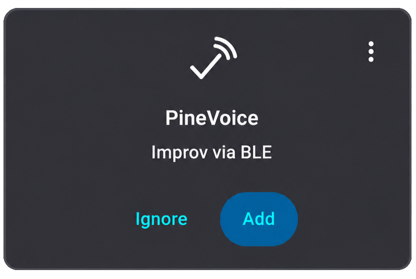
Improv card in Home Assistant
After successful Wi-Fi provisioning, continue with assistance setup.
Assistance setup
PineVoice implements the open-source Wyoming protocol for voice assistants. Any assistance application supporting this protocol can communicate with PineVoice.
After PineVoice has joined the Wi-Fi network, the center ring LED should slowly breathe in a dim magenta color. This means PineVoice is connected to Wi-Fi and is waiting for an assistance application to connect through the Wyoming protocol.
Adding PineVoice to Home Assistant
Home Assistant supports Wyoming Protocol devices through the Wyoming Protocol integration. Home Assistant must also have a working Assist voice pipeline. Follow the Home Assistant Assist documentation if Assist has not been configured yet.
Automatic setup
PineVoice supports mDNS auto-discovery. If Home Assistant can see mDNS announcements on the same network, PineVoice should appear automatically as a discovered Wyoming Protocol device.
- Open Home Assistant.
- Go to Settings -> Devices & services.
- Look for a discovered Wyoming Protocol device.
- Select Configure.
- Follow the on-screen instructions to finish adding PineVoice.
After setup completes, PineVoice should be available as an Assist satellite in Home Assistant.
Manual setup
If PineVoice does not appear automatically, add it manually through the Wyoming Protocol integration.
- Find the IP address of PineVoice in the client list of your Wi-Fi router or access point.
- Open Home Assistant.
- Go to Settings -> Devices & services.
- Select Add integration.
- Search for and select Wyoming Protocol.
- Enter the PineVoice IP address as the host.
- Enter
10700 as the port.
- Follow the on-screen instructions to finish adding PineVoice.
Troubleshooting
Known issues currently being investigated:
- If PineVoice is stuck in the listening state or Home Assistant does not react when Assist starts, restart PineVoice.
- If adding the device fails, press Retry / Try Again, or try to add PineVoice again.
If Home Assistant cannot connect to PineVoice, check the following:
- PineVoice and Home Assistant are on the same network or VLAN.
- The center ring LED is breathing in dim magenta.
- The IP address entered in Home Assistant is the current IP address of PineVoice.
- TCP port
10700 is reachable from the Home Assistant system.
- mDNS is allowed on the network if using automatic discovery.
For more information, see the Home Assistant Wyoming Protocol integration documentation.
Testing
After PineVoice is added to an assistance application, Assist can be triggered in the following ways:
- Say the wake word: "Hey Jarvis"
- Press the center button in the LED ring
After triggering Assist, say a command supported by the assistance application. The assistance application should reply accordingly.
LED ring lightshows and controls
The center LED ring shows the current state of PineVoice. For most actions and states, light shows are used instead of voice feedback so PineVoice does not unexpectedly disturb the user, for example during the night. Active-state light shows, such as the dim cyan standby light, are intentionally kept dim so they remain visible without being distracting in a dark room.
Startup and setup
| Light show
|
Meaning
|
| Dim white fade-in/fade-out, once
|
Boot-up lightshow. PineVoice has started.
|
| Yellow breath, loop
|
PineVoice is in provisioning mode and is ready to connect to Wi-Fi through the Improv protocol.
|
| Green fade-in/fade-out, once
|
Identification signal during provisioning, used to identify the paired PineVoice.
|
| Dim orange breath, loop
|
PineVoice is trying to connect to Wi-Fi.
|
| Dim magenta breath, loop
|
PineVoice is waiting for a Wyoming client to connect.
|
Assistant states
| Light show
|
Meaning
|
| Dim cyan, still
|
PineVoice is active and in standby, waiting for the user to press the center button or say the wake word.
|
| Blue-cyan-blue breath, loop
|
PineVoice is listening to the user's voice input.
|
| Dim purple, still
|
PineVoice is processing the user's input.
|
| Slow green breath, loop
|
PineVoice is answering.
|
Action feedback
| Light show
|
Meaning
|
| White fade-in, once
|
Volume up.
|
| White fade-out, once
|
Volume down.
|
| Red fade-out, once
|
An error happened or the action failed.
|
Button controls
PineVoice has five top buttons for voice control, volume, microphone mute, and provisioning.
- Center LED ring button - starts a voice command session.
- + button - increases the volume.
- - button - decreases the volume.
- Microphone button - hardware microphone mute. The button shines red while microphone mute is active.
- Dot / user button - currently used to enter provisioning mode. Hold it for 15 seconds to reset Wi-Fi setup and return PineVoice to provisioning mode.
Voice feedback and wake word detection
PineVoice mostly uses light shows instead of voice feedback. Voice feedback is generally reserved for direct user interaction.
Audio feedback is currently used in the following cases:
- Wi-Fi provisioning started - played when Wi-Fi provisioning starts, including on first boot.
- Wi-Fi provisioning succeeded or failed - played when Wi-Fi provisioning finishes successfully or fails.
- Wyoming satellite is disconnected - played when Assist is attempted, but the Wyoming satellite/client is not connected.
- Wi-Fi is disconnected - played when Assist is attempted, but PineVoice is not connected to Wi-Fi.
PineVoice uses MicroWakeWord for local wake word detection.
For now, PineVoice uses the "Hey Jarvis" model from the ESPHome MicroWakeWord models project. Wake word recognition may vary depending on the speaker's voice, pronunciation, distance from the device, and background noise.
Future firmware updates are expected to add support for custom MicroWakeWord-compatible models. There are also plans to train a PineVoice-specific wake word model. If you are interested in helping with model training, contact us through the community channels.
Board information, schematics and certifications
Module dimensions:
Production version schematics:
Certifications:
Datasheets
Bouffalo BL606P SoC information:
SPI NOR flash information:


