Difference between revisions of "Model B Acrylic Open Enclosure"
m (Fxc moved page "Model B" Acrylic Open Enclosure to Model B Acrylic Open Enclosure: Streamlined naming) |
(fixes) |
||
| Line 2: | Line 2: | ||
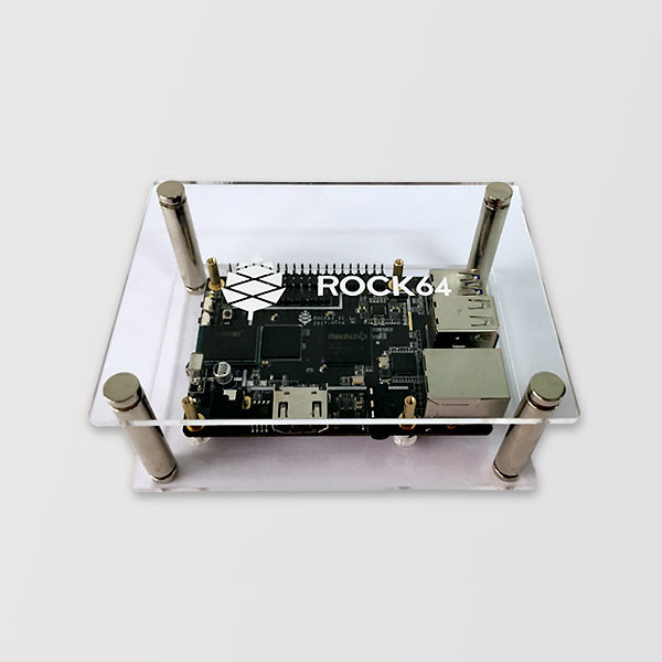
The '''"Model B" Acrylic Open Enclosure''' is a case for "Model B" sized single-board computers sold by PINE64, available from [https://pine64.com/product/model-b-acrylic-open-enclosure/ the official store]. | The '''"Model B" Acrylic Open Enclosure''' is a case for "Model B" sized single-board computers sold by PINE64, available from [https://pine64.com/product/model-b-acrylic-open-enclosure/ the official store]. | ||
= Installation = | == Installation == | ||
To install the SBC inside the case, stick the long screws into the SBC mounting holes from below, place the board such that the screws sit in its mounting holes, and screw on the brass fasteners on top of the SBC. | To install the SBC inside the case, stick the long screws into the SBC mounting holes from below, place the board such that the screws sit in its mounting holes, and screw on the brass fasteners on top of the SBC. | ||
= Mods = | == Mods == | ||
== 3D-Printable Top With Fan Cutout == | === 3D-Printable Top With Fan Cutout === | ||
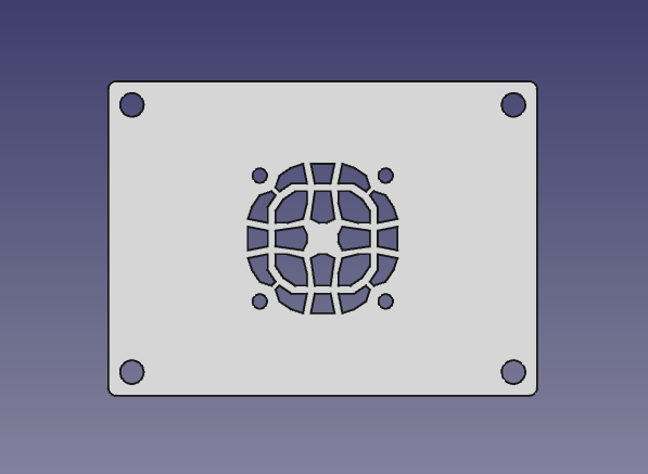
[[File:Model b open enclosure top cad.png|thumb|Top view of the plate]] | [[File:Model b open enclosure top cad.png|thumb|Top view of the plate]] | ||
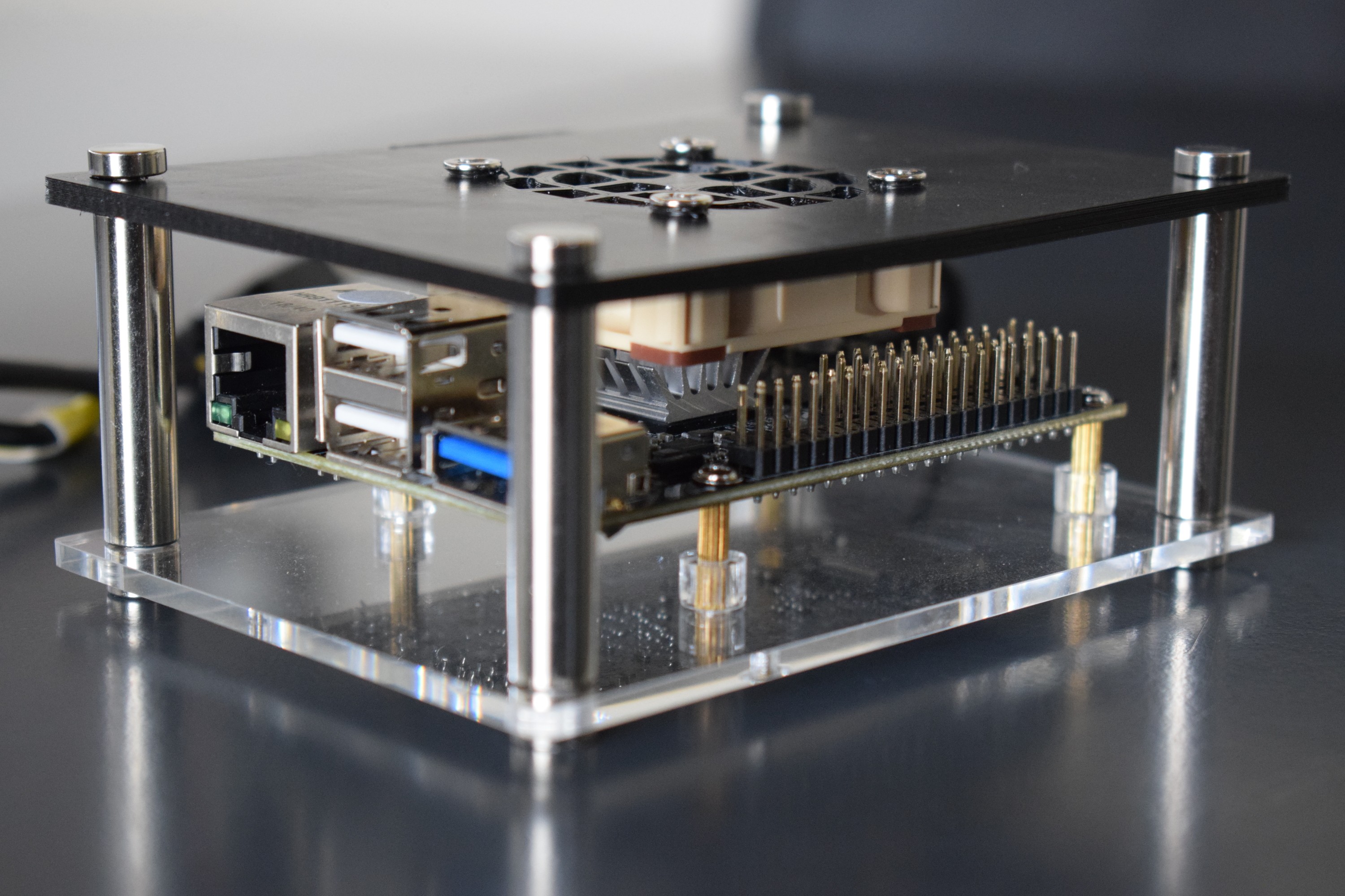
[[File:Model B Open Enclosure Top Fan Mount.jpeg|thumb|The assembled modified case with a Noctua NF-A4x10 5V PWM mounted to it. The SBC is mounted in the enclosure upside-down.]] | [[File:Model B Open Enclosure Top Fan Mount.jpeg|thumb|The assembled modified case with a Noctua NF-A4x10 5V PWM mounted to it. The SBC is mounted in the enclosure upside-down.]] | ||
Latest revision as of 21:29, 2 April 2023
The "Model B" Acrylic Open Enclosure is a case for "Model B" sized single-board computers sold by PINE64, available from the official store.
Installation
To install the SBC inside the case, stick the long screws into the SBC mounting holes from below, place the board such that the screws sit in its mounting holes, and screw on the brass fasteners on top of the SBC.
Mods
3D-Printable Top With Fan Cutout
User:CounterPillow has created an alternate 3D-printable top plate which allows for the mounting of a 40mmx40mmx10mm fan. The STL and STEP files are available free of charge, licensed as CC-BY 4.0.
A fan is mounted to it using self-tapping fan screws usually shipped with computer fans; put the fan on the underside of the plate, and screw in the self-tapping screws from the top side. You can either have the fan exhaust air through the top, or blow it onto the SoC's heatsink. The latter configuration appears to work better, but precise measurements haven't been made yet.
Recommended printing material is PETG for its structural rigidity. However, PLA will likely work fine as well, and is easier to print. A 0.6mm nozzle was used for test prints, but any nozzle should work. Depending on the layer height you choose, your print may come out slightly thicker or thinner; this is no problem though. It's recommended to enable the advanced "Detect Thin Walls" option in slic3r to get a cleaner g-code result around the fan holes.
The print will take approximately 7.8 metres of filament, and take in the order of one hour, though this depends on slicer settings and printer model.
The cooling performance with a Noctua NF-A4x10 5V PWM is enough to no longer throttle after a few minutes of cpuburn, but comfortably sitting at below 75°C instead. The memory has no temperature sensor, but will likely be cooled quite a bit as well.
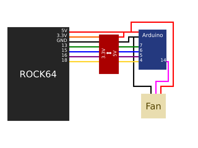
Since the ROCK64 has no PWM pins available to control the fan, a slight workaround can be done; with the gpio-fan device tree binding, an Arduino can be controlled to soft-PWM a suitable 25 kHz signal for the fan. The ROCK64 uses 3.3V on the GPIO pins, so you'll need to logic level convert it to 5V if you're using a 5V Arduino, and if you're using a 3.3V microcontroller, you'll need to logic level shift the output PWM signal as the 5V fan will be expecting 5V PWM on the PWM pin.
The device tree changes and the Arduino sketch which User:CounterPillow created for this can be used for any purpose by anyone. It is recommended to play around with the device tree though, to add more trip points for better control over when the fan actually ramps up, and adding more hysteresis as the temperature reading from the ROCK64 is quite jumpy.


