Project Don't be evil

The Project Don't be evil is the phase two of PINE64's smartphone, the PinePhone Development Kit. Project Don't be evil is an actual smartphone developer kit for the PINE64 Smartphone dubbed "PinePhone". It is used in the early stages of development as a starting point for affiliated projects.
The PinePhone development has been broken down into three distinct phases:
- First phase - Project Anakin
- Second phase - purpose-built development kit code named "Don't be evil" and introduced at FOSDEM 2019
- Lastly, the third phase which is the PinePhone itself - scheduled to be prototype released in Q3 2019 and BTO batch released with mobile OS parents in Q4 2019 (pending on software development).


Baseboard and SOPine Module Information, and Schematics
- Baseboard Dimensions: 165mm x 76mm x 19.5mm
- Input Power: DC 5V @ 2A, 3.7V Li-Ion battery connector, USB type-C connector
Baseboard Schematic:
- "Don't Be Evil" PinePhone Dev kit Baseboard Structure
- "Don't Be Evil" PinePhone Dev kit Baseboard Ver 1.1 Schematic
- "Don't Be Evil" PinePhone Dev kit Baseboard Ver 1.1 PCB Artwork
- "Don't Be Evil" PinePhone Dev kit Baseboard Ver 1.2 Schematic
- "Don't Be Evil" PinePhone Dev kit Baseboard Ver 1.2 PCB Artwork
SOPine Module Schematic:
Wifi/BT module information:
Pin assignment:
SoC and Memory Specification
Based on the Allwinner A64/R18. The R18 and A64 are identical SoC but R18 committed for 10 years supply by vendor.


CPU Architecture
- Quad-core ARM Cortex-A53 Processor@1152Mhz
- A power-efficient ARM v8 architecture
- 64 and 32bit execution states for scalable high performance
- Support NEON Advanced SIMD (Single Instruction Multiple Data) instruction for acceleration of media and signal processing function
- Support Large Physical Address Extensions(LPAE)
- VFPv4 Floating Point Unit
- 32KB L1 Instruction cache and 32KB L1 Data cache
- 512KB L2 cache
GPU Architecture
- ARM Mali400MP2 Dual-core GPU
- Support OpenGL ES 2.0 and OpenVG 1.1 standard
System Memory
- RAM Memory Variants: 2GB LPDDR3.
- Storage Memory: SPI Flash and optional eMMC module from 16GB up to 64GB
Datasheets for Components and Peripherals
Allwinner A64/R18 SoC information:
- Note: the R18 and A64 are identical SoC but the R18 is committed for a 10 years supply by the vendor.
- Allwinner A64 SoC Brief Introduction
- Allwinner R18 SoC Brief Introduction
- Allwinner A64/R18 SoC Data Sheet V1.1 (Official Released Version)
- Allwinner A64/R18 SoC User Manual V1.0 (Official Release Version)
X-Powers AXP803 PMU (Power Management Unit) information:
LPDDR3 information:
eMMC information:
- PINE64 eMMC module schematic
- PINE64 USB adapter for eMMC module V2 schematic
- PINE64 USB adapter for eMMC module PCB in JPEG
- SanDisk eMMC Datasheet
- Hynix eMMC Datasheet
- Foresee eMMC Datasheet
SPI NOR Flash information:
Related datasheets
2MPixel front CMOS Camera module information:
- 2MP CMOS Image Sensor Module Drawing
- GalaxyCore GC2035 2MP CMOS Image Sensor Product Brief
- GalaxyCore GC2035 2MP CMOS Image Sensor Datasheet
5MPixel Rear CMOS Camera module information:
- 5MP CMOS Image Sensor Module Drawing
- OmniVision OV5640 5MP CMOS Image Sensor Datasheet
- OmniVision OV5640 5MP CMOS Image Sensor Software Application Note
LCD Touch Screen Panel information:
- 5.7" 1440x720 IPS LCD Panel Specification
- fiti JD9365D LCD Controller Datasheet
- 5.7" Front Panel Touch Screen Specification
- FocalTech FT6336GU Front Panel Touch Screen Specification
Lithium Battery information:
Ethernet PHY information:
Wifi/BT module information:
LTE module information:
- Quectel EC25 LTE Module Specification
- Quectel EG25-G LTE Module Specification
- Quectel EC25 LTE Module AT Cammands Set Manual
- Quectel EC25 LTE Module Hardware Design Guide
- Quectel EC25 LTE Module Reference Design Guide
Sensors:
- ST LIS3MDL 3-axis Magnetomater Datasheet
- InvenSense MPU-6050 Six-Axis (Gyro + Accelerometer) MEMS Datasheet
- SensorTek STK3335 Ambient Light Sensor and Proximity Sensor
Software releases
Some these OS images labelled as beta or nightly builds which means they are only fit for testing purposes. These images should be used at your own risk and are not fit for normal use.
postmarketOS
Download:
Instructions:
Notes:
- postmarketOS early alpha test build for microSD boot
- for 8GB microSD cards and above
- Suitable for PinePhone "Don't Be Evil" Dev Kit version 1.1 and version 1.2
- There are two type of LCD panels. For long touch screen cable, please use the build with inverted wording.
Sailfish OS
The Sailfish OS image is build on Gitlab CI, the latest image can be installed using our flashing script written in Bash.
The script downloads the image and bootloader from our CI, extracts everything and burns it onto the SD card.
Instructions:
- Download the flashing script
- Insert a microSD card in your device
- Make the script executable:
chmod +x flash-it.sh - Execute it:
./flash-it.sh - Follow the instructions. Some commands in the script require root permissions (for example: mounting and flashing the SD card).
Notes:
- The script will format and flash the SD card, make sure that you don't have any important data on the SD card!
Maemo Leste
Download:
Notes:
- Works on dev kit versions 1.1 and 1.2
- Write the image to a micro SD (8GB+) or eMMC
LuneOS
Download:
Notes:
- It is recommended to use bmaptool
- for example
bmaptool copy https://build.webos-ports.org/luneos-testing/images/pinephone/luneos-dev-image-pinephone-testing-0-15.rootfs.wic.gz /dev/mmcblk0
Mali Driver
For the Mali driver see Mali_Driver.
Errata for ver1.1 and ver1.2 board
1. Please DON'T insert micro SIM card to dev kit board micro SIM card slot, the SIM data, VPP, and GND signal have been misplaced. A miciPCIe adapter with sim card holder 9shown as below photo) will be provide to developers to correct this mistake.

2. The PinePhone dev kit doesn't charge due to VBUS on SOPine module is not connected. Please connect R9688 solder pads with 0 ohm resistor or using thin wire bridge up the solder pads. Location shows as below:

3. The SOPINE's SPI NOR flash storage and the devkit's camera flash (heh) share the same GPIO pins. The flash storage may not be used.


4. On the camera flash GPIO conflict, the new assignment of GPIO PB3 pin for SGM3140 FLASH_EN and GPIP PD7 for FLASH_TRIGOUT. Please note that PD7 is also LCD_ID pin which may not be used.
Images:
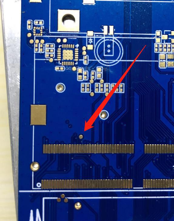
GPIO PB3 location
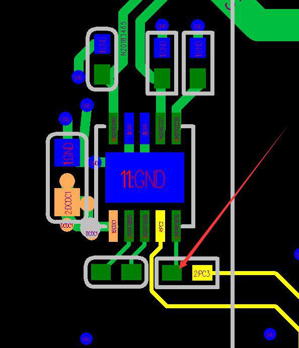
U54 SGM3140 FLASH_EN pin location
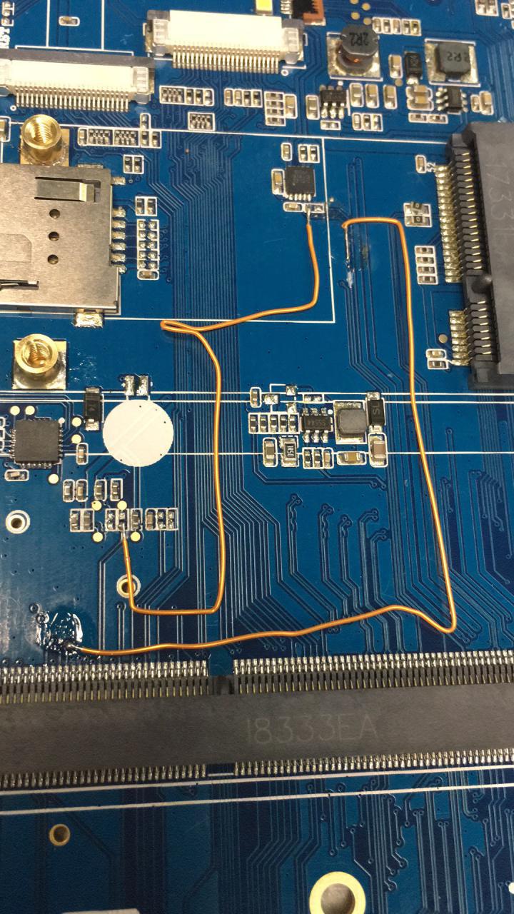
Flash GPIOs Reassigned wiring


